


Fluffy
-
Posts
76 -
Joined
-
Last visited
Content Type
Forums
Calendar
Gallery
Posts posted by Fluffy
-
-
Personally I can't wait to renew my 3D Coat license for another year! I think all the work that Andrew and Co. have put into the latest updates have more than justified the extremely reasonable renewal fee and while there are some outstanding bugs & issues when you consider the huge amount of new features and improvements it's completely unrealistic to expect that much advancement without a few teething problems. You only have to compare the list of new features and improvements for 3D Coat in the last year to any other 3D app (even those with a much larger group of developers working on them) to see that you're getting your moneys worth when renewing your license!
Sadly it looks like I'm going to have to wait a little while longer due to the fact that the upgrade option on the store page currently isn't working for me!

However I'm sitting here with a fist full of €€€ eagerly waiting for Pilgway to...

-
 1
1
-
 2
2
-
-
Anyone else having issues with license renewal?
My license for 3D Coat ran out a couple of weeks ago and I just discovered that I'm unable to renew it via the store page.
According to my account page I have 2x 3D Coat licenses...
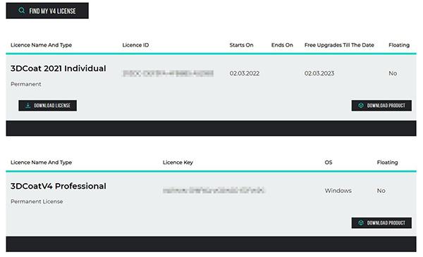
but when I go to the store page and try to use the upgrade option I get a message saying an upgrade for the V4 license is already in my cart...

however when I then go to view the cart it's empty

So, despite apparently owning 2 licenses for 3D Coat I'm unable to renew my license and am currently stuck in learning mode!
Anybody have any ideas?
-
32 minutes ago, NLPLP said:
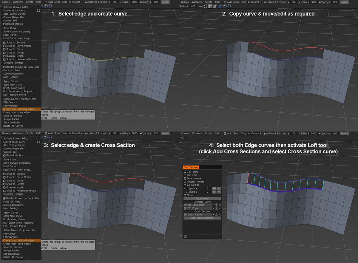
Is it possible to loft between mesh edges and a curve in the polygon environment?
Yes, using the Loft tool and the same process I outlined in this post...
To recap, just select the edge you want to loft and choose Create from selected edges from the Curves menu then select the newly created curve and your original curve and activate the Loft Surface tool in the Add Geometry panel...
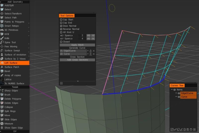
... then just set your V Spans, check your normals are pointing the right way and hit Apply Mesh.
-
1
-
-
2 hours ago, phoenixart said:
Thanks @Fluffy for checking.
I wasn't sure whether I had to delete the geometry or not before proceeding with Res+
In the first video I posted around 59 seconds in, I do delete the geometry, and then increase the resolution, but the problem still persists.
During my tests, it seemed that this is a random behavior. Sometimes I restart 3D Coat, go through the same steps, and it works. Other times it doesn't, and what's worst, after I save and reopen the scene, I find the original mesh intact, with no hidden voxels whatsoever.
Not sure how to help to nail down where the issue lies.
Okay, I followed the steps you took in that part of the video and I found that if you increase the layer resolution and then revert using the Undo option once then Delete Hidden doesn't have any effect and increasing the layer resolution will result in the voxels being unhidden just as you described.
After a little more testing I noticed that there seems to be a few inconsistencies with using the Undo option in conjunction with Separate Hidden Volumes (for example, if you use the Undo feature directly after selecting Separate Hidden Volumes you'll find that it reverts the creation of the voxels but doesn't remove the newly created empty layer).
With this in mind I went back and tested your exact process again and discovered that if, after increasing the resolution of the sculpt object, you hit Undo twice before selecting Delete Hidden the hidden voxels will be deleted and you can increase the layer resolution without the hidden/deleted voxels reappearing.
It seems like the issue is also somehow related to using Undo to revert changes to the object resolution. The last thing I tried involved the following steps:
- Create a voxel object.
- Hide part of the object with VoxHide.
- Select Separate Hidden Volumes from Geometry menu to create new Sculpt Object.
- Select original voxel object and increase resolution (hidden volumes become visible).
- Revert changes with Undo.
- Select Delete Hidden from Geometry menu.
- Increase resolution of original voxel object ("deleted" volumes become visible).
- Select Undo option 3 times.
- Select Delete Hidden from Geometry menu.
- Increase resolution of original voxel object (volume created successfully).
Result:
It seems like you need to use the Undo option twice to fully revert the changes to layer resolution and, based on the number of times Undo was used in step 8, the issue "stacks" so that each time you only select Undo once in order to try a different approach it will require an additional Undo in order to revert to a point where Delete Hidden works correctly.
In short, the best solution for now seems to be ensuring that you always select Delete Hidden from the Geometry menu before attempting to increase the layer resolution.
ETA: An alternative solution is to duplicate the original Sculpt Object, increase the resolution of the newly created copy and just delete the original, since duplicating an object doesn't duplicate hidden voxels (Note: apparently this method is still affected by the same issue with Undo i.e. if you increase the layer resolution and then hit Undo once before duplicating the layer the hidden voxels will also be duplicated but if you hit Undo twice after increasing the resolution then duplicating the layer removes the hidden voxels as expected).
-
1
-
1
-
On 1/25/2023 at 6:43 PM, phoenixart said:
Here are the steps:
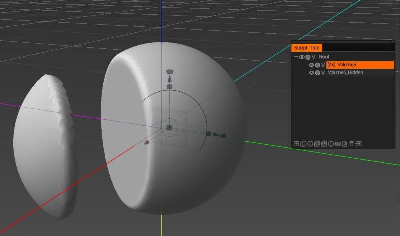
- Use Vox Hide to hide part of the voxel mesh.
- Separate the hidden parts.
- On the original voxel mesh, increase the resolution. The hidden parts come back, and they're now joined to the original mesh.
Seeing the same behaviour in 3D Coat 2022.57, it also happens if you use the Unhide All option.
On 1/25/2023 at 6:43 PM, phoenixart said:Alternatively, before step three, use first Delete Hidden Parts prior to increasing the resolution. The result doesn't change.
Tested this several times and I'm not seeing the same behaviour. After separating the hidden parts and selecting the original sculpt layer using Delete Hidden prior to Unhide All seems to fix the issue.
On 1/25/2023 at 6:43 PM, phoenixart said:Lastly, save the file, and re-open it. Now the original mesh it's back, and the hidden parts are again visible in the original layer.
It appears that the Separate Hidden Parts option doesn't actually remove the hidden voxels when it creates the new objects and I don't believe hidden voxels persist between saving/reloading so this would probably be considered expected behaviour.
It's either a bug or a misnamed feature since currently Separate Hidden Volumes seems to function as "Clone Hidden Volumes".
ETA: Just noticed @Carlosans added comment concerning Separate Hidden Volumes copying rather than removing voxels, perhaps just changing the wording of the tooltip for the feature from "Creates a new Sculpt Object from hidden parts of volumes" to "Clones hidden parts of volumes to create a new Sculpt Object" would help to avoid confusion in future?
-
1
-
1 hour ago, Oleg_Shapo said:

Why not use the new, incredibly powerful Curves functionality?
!00% this! ^^^
@NLPLP Using Curves would be a much better solution, especially paired with the Coat tool (which can be accessed by right-clicking a curve and choosing Fill with Mesh Layer) which not only allows you to assign custom contours for your extruded edge...

... you can modify the shape at any time after creating it (until you intentionally detach the curve from the object)...

-
2
-
-
2 hours ago, NLPLP said:
Please see video I made and let me know if there s a way to fix this
I really do not understand this behavior as it serves no purpose and Im hoping Im doing something wrong .
If not this must be a bug.
This is just a hunch but are you rotating the camera by holding down the ALT key?
One of the new features in 3D Coat is the ability to rotate splines by holding down the ALT key which automatically detaches the spline from the surface while the ALT key is pressed. Instead of using the ALT key to navigate try left-clicking and dragging in the border area of the viewport and see if the spline remains attached to the surface.
-
2
-
-
3 hours ago, phoenixart said:
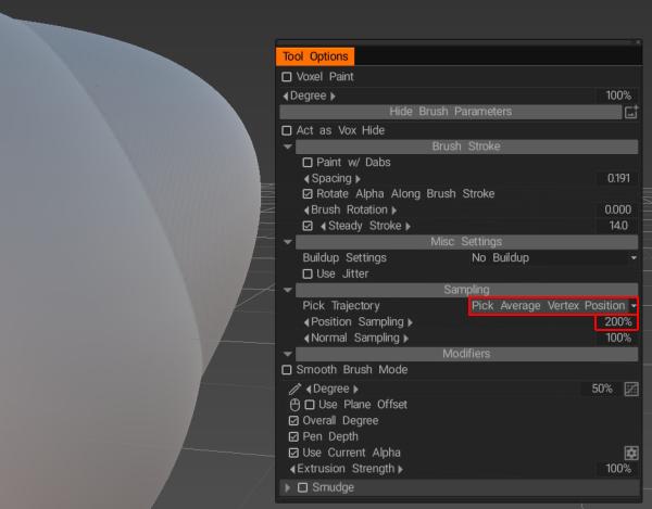
Hm... it seems it's a bug. It works with the other brush mode, like radius, depth, vertex curve, curve, but when I switch to stamp than the issue shows up.
It seems like using the Stamp tool at really large sizes on a curved surface can lead to protruding edges if the projected edge of the brush alpha falls too far from the surface you're applying it to. In order to avoid disconnected/protruding edges try swapping the Pick Trajectory setting to Pick Average Vertex Position and setting the Position Sampling value to 200%.
-
2
-
-
1 hour ago, AbnRanger said:
What build are you using? As you can see in the GIF above, with build 57 I get absolutely nothing.
Try working in select edges rather than select vertices and selecting just the edges that you want to rearrange into a circle (you won't see any preview as you would when aligning to a plane so you'll need to hit Apply to see the results).
 11 minutes ago, Gorbatovsky said:
You must to select Face for align by circle
I just tried Faces, Vertices and Edges but could only get it to work with edges selected.
-
6 hours ago, Deano C said:
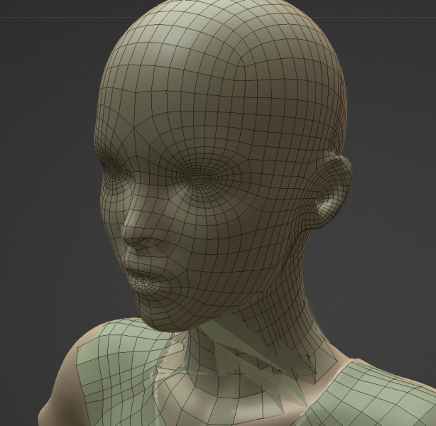
Manually retopo'ed the head, add it to a poly group, hid it. Did some work woth on the body and legs, then unhid the head and its corrupted (polygons at the neck). This isn't the first time that hiding polygroups get corrupted, fix it up and a bit latter another group will get corrupted.
So that its basically not possible to segment up the retopo process, as you can almost guarantee that working on one group will be corrupting a different hidden one *sigh*.
Without knowing a bit more about the steps you're taking that cause this issue it's going to be difficult to reliably reproduce the results you're getting, however I've personally found that one of the most common causes of hidden polygroups getting deformed in a way similar to what you're describing occurs when a collection of connected polygons are split across multiple layers (especially when the Auto Snap or Conform Retopo Mesh options are enabled).
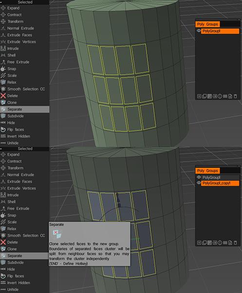
Since selecting faces of an object and moving them to a different polygroup doesn't separate them from the remaining faces it can occasionally lead to those hidden but still connected faces being affected by operations performed on any other polygroup that contains polygons connected to the hidden faces/groups.
In order to ensure that doesn't happen you can select the faces you wish to move to a new polygroup and choose the Separate option in the Selected section of the Tools panel which will, as the name suggests, separate the selected faces from the rest of the poly object before moving them to a new polygroup.
If you need to merge the separated faces with the rest of the object again later you can simply select the necessary faces, move them back to their original layer and use the Weld Vertices tool (also located in the Selected section of the Tools panel) to merge the vertices along the edges.
-
10 minutes ago, NLPLP said:
Thanks Fluffy thats what I wanted.
Its weird though Smart extrude is not in my toolset or the right click menu when I have an active edge selection
Yes Im running the trial version of 2022.57
For me it's located in the Add Geometry panel in both rooms (but you should also be able to find the Smart Extrude tool in the Tools Palette in either room by pressing spacebar or opening it via the Windows>Panels menu). It may be that it's just not immediately visible in the left panel since some tools are grouped together differently in different rooms.
In the Modeling room the Smart Extrude tool is grouped with the Spine Tool and InSet tools, while in the Retopo room it's grouped with the other extrusion tools (Free Extrude, Normal Extrude, Extrude Faces & Extrude Vertices)...
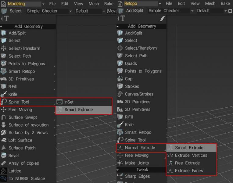
If you don't see it displayed in the left panel then try looking for one of the other tools in the same group and hovering your mouse over it.
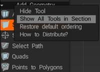
If you still can't find it try right-clicking any of the tools in that section and selecting the Show All Tools in Section option just in case it's gotten hidden somehow.
-
1
-
-
4 hours ago, NLPLP said:
I was thinking something along the lines of the solidify modifier in Blender.
Try the Shell tool.
First select the faces you want to "solidify" then activate the Shell tool...
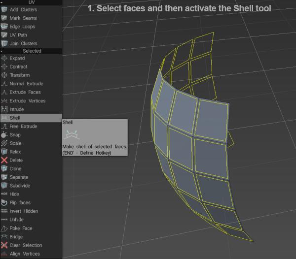
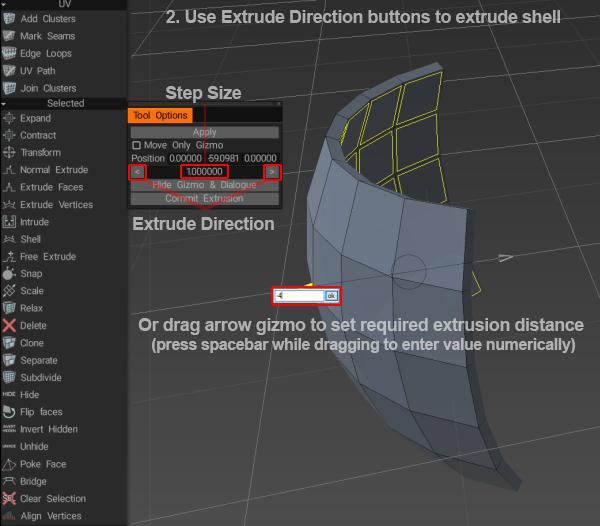
then use the buttons in the Tool Options window or the arrow gizmo to set the amount of extrusion...
 4 hours ago, NLPLP said:
Also there's no smart extrude on the latest build.....maybe it was taken out?
Which version are you using? I have 2022.57 and the Smart Extrude tool is available in both the Modeling and Retop rooms.
-
2
-
-
9 minutes ago, Oleg_Shapo said:
The Loft and Smart Retopo tools are currently in development. An update should be out soon. These tools are not yet very friendly, so we are waiting for an update.
That's good news. The current tools do take a little effort to work out but once you get the hang of them they're extremely useful. I'm a lot more familiar with using the Sculpt room to block things out first so I'm still getting to grips with some of the newer low poly modelling tools but so far I'm enjoying them a lot!
-
1
-
-
On 1/14/2023 at 9:41 PM, NLPLP said:
Thanks for the response.
No I want to do what Oleg showed in his response above (mostly because it adops the flowfrom the edges below), but the only problem is that the
Loft Surface tool does not work with edges for me, only curves
I'm not that familiar with the Loft tool but I think I managed to figure out the process that Oleg is illustrating in the screenshot (it became a little clearer once I realised the selected edge shown was obscuring the third curve used in the loft operation).
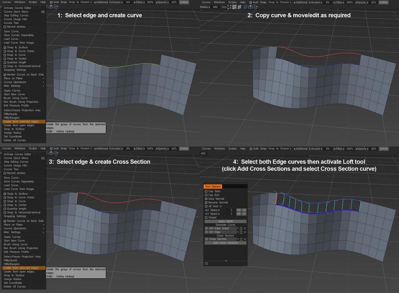
It's worth noting that the order in which the two profile curves appear in the Tool Options window can have an effect on the resulting mesh. The number of knots in the first curve in the list (in conjunction with the value set for U Spans) determines the number of polygons created and the order in which the curves appear determining the direction of the vertex normals on the resulting mesh. Additionally if the curve which defines the edge you intend to create appears first in the list then the result when you hit apply may not align correctly with your existing mesh (without going into too much detail it seems to have something to do with how vertex normals effect the way in which 3D Coat generates the lofted surface).
Adding the Cross Section curve created in Step 3 appears to solve the issue regardless of the order the Profile curves are listed in however it can sometimes flip the vertex normals of the resulting mesh so it's a good idea to enable the Draw Normal option and then you can toggle the Reverse Normal setting if needed.
As I said I'm not that familiar with the Loft tool but this seems like a fairly reliable way to retrieve the desired result, however I personally prefer the Smart Retopo tool which can achieve very similar results using less curves.
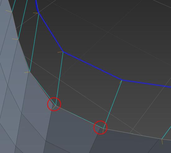
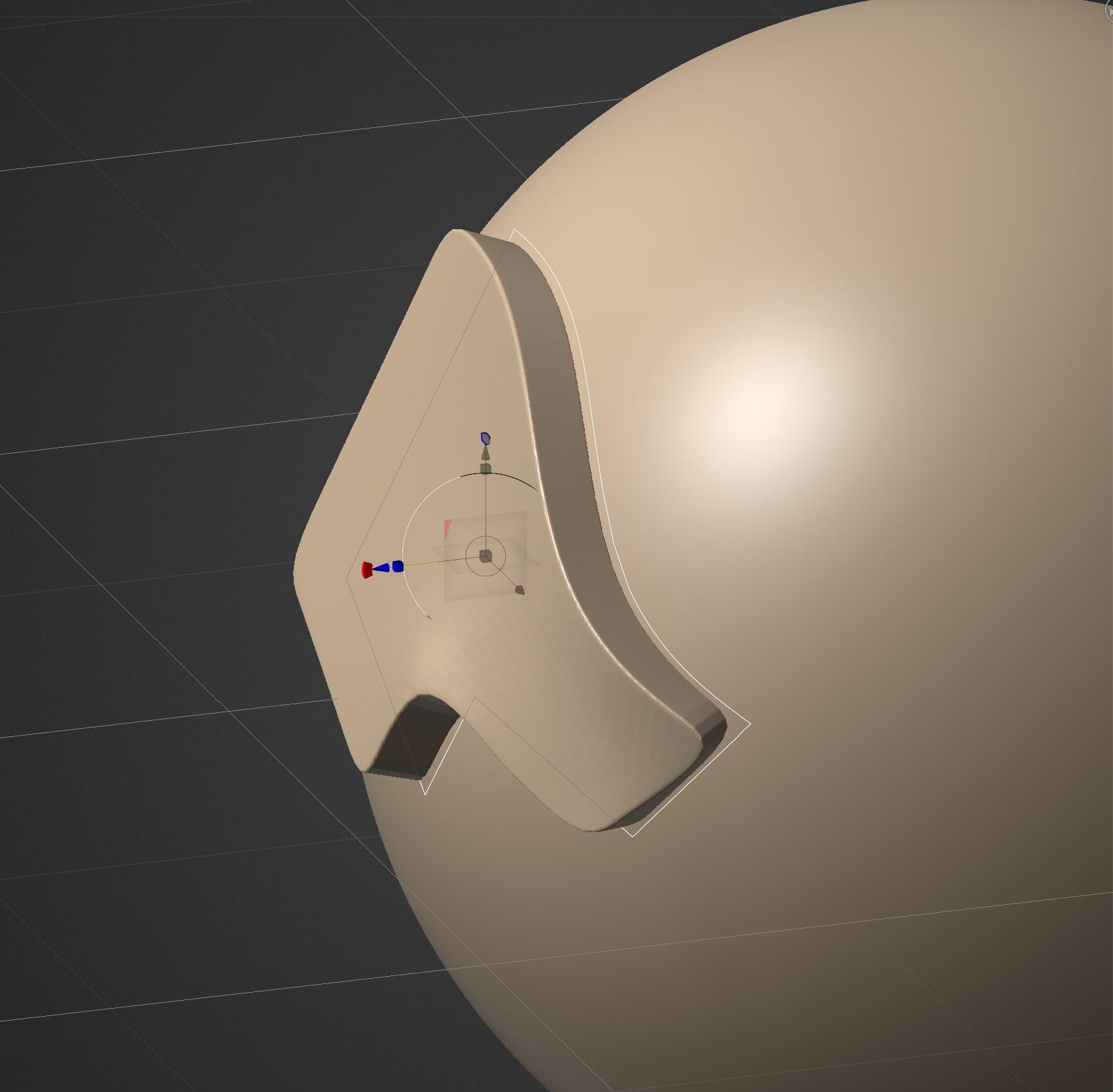
All you need to do is create a curve for the edge you wish to generate and then activate the Smart Retopo tool, set the Mode to Quadrangulation, press the Add Profile button and select the curve and then set the required number of U Spans. You may need to quickly tweak the position of each end of the curve to make sure it snaps to the correct vertices on the existing mesh but once both ends are correctly positioned you should see something like this...
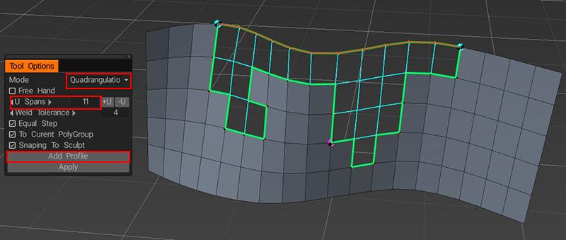
(at first you should only see the green border, but if you hit the Apply button it will preview the results and hitting the Apply button a second time will generate the mesh).
As you can see the Smart Retopo tool is capable of filling irregular shapes which could potentially be problematic and/or time consuming using the Loft tool, but I'd still recommend learning how to use both. As with most things in 3D Coat there are multiple ways to achieve the same results and which method works best very much depends on your personal preference and overall workflow, hopefully the above information will help you figure out which approach works best for you.
")
-
2
-
-
In addition to what @Carlosanposted above which works with Use Current Alpha enabled, you can also use the Presets panel to store the current settings for a specific tool (including any alpha shape you create using the Edit brush shape window). Just right click in the Presets window and choose Add Preset.
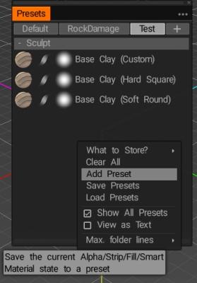
You can choose which particular settings are stored by enabling or disabling them via the What to Store? menu
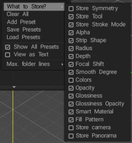
If you want to make any alterations to the preset after you've created it you can right-click it and choose Update Preset (you can also rename the preset, add your own description for the mouseover popup window and add the preset to one of the numbered slots in the Quick Panel via the same menu).
-
1
-
-
16 hours ago, Glitch Gremlin said:
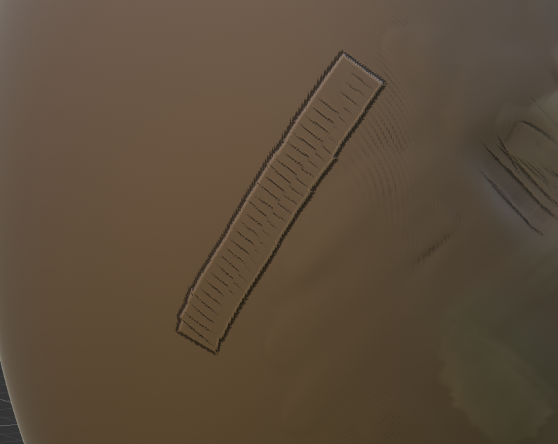
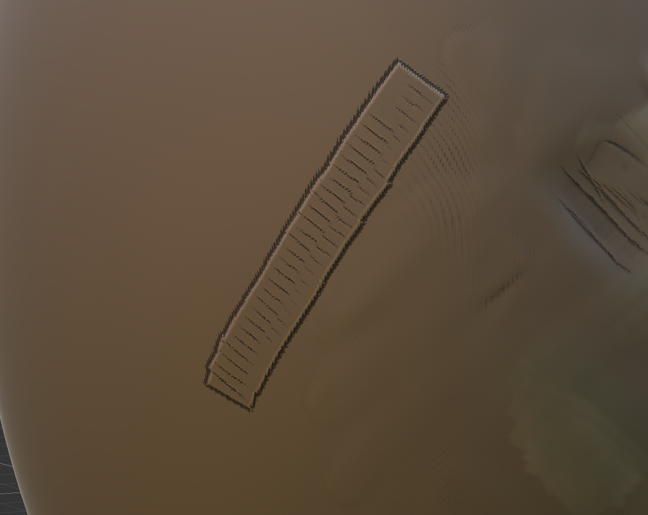
Hey guys. im trying to do better with the brushes and stuff in 3D Coat, but when i sculpt with them the Alpha "I guess they're called Alphas in 3D Coat?" are SUPER Strong and sharp. i want to have control for doing Organic or really sharp edges, how would i go about that? here is an image of what im talking about in case im not explaining it right
but im just trying to get the sculpting to be as close to Zbrush or Blenders as possible, cause i love this program and the Voxels, but i just can't seem to find the Brush settings im after. or im doing it wrong, going in with the wrong mindset? no idea.
thanks for any help you can provide.
Without more of an idea of which brushes you're using and the type of result you're trying to achieve it's a little hard to know where to start (how to use brushes/alphas in 3D Coat is a pretty broad subject and would probably take a while to get through).
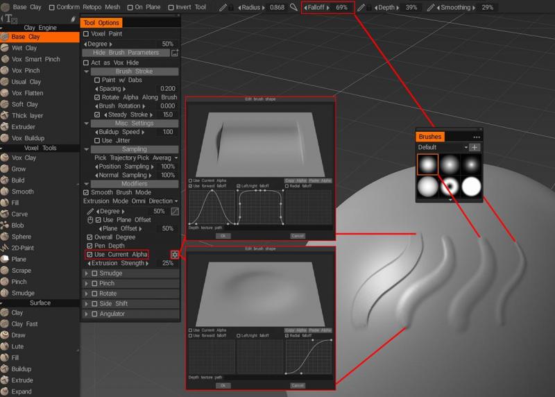
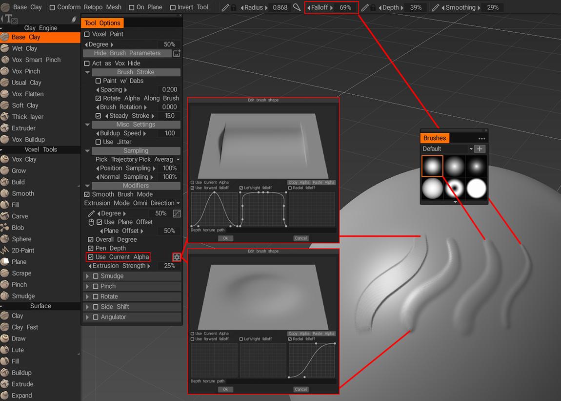
Tools like Grow in the Voxel Tools panel incorporate smoothing automatically and will give you very smooth, organic results without any need to tweak the settings, but if you're working with the tools in the Clay Engine panel here's a couple of settings that may help...
Using the Base Clay tool as an example, if you look at the Tool Options you'll see a checkbox for Use Current Alpha and next to it a gear icon. While the Use Current Alpha option is disabled you can use the gear icon to access the Edit Brush Shape options window where you can modify the brush shape for the current tool. Alternatively with the Use Current Alpha option enabled you can select any brush/alpha from the Brushes panel and additionally you can further vary the edge blending by changing the Falloff value. Here's a screenshot with the various settings and the resulting brush strokes...
-
1
-
-
At first glance it seems like it should be inverted, but if you pop the Layers window out from its docked position and increase the width of the window you can see the full title of that setting isn't Roughness...
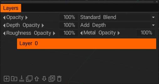
...it's actually Roughness Opacity and in that context it works exactly as you would expect it to, i.e. it controls the opacity of the roughness channel of the layer rather than the roughness value itself.
-
1
-
-
Out of curiosity, have you checked your scene scale for any of the models which aren't working?
I ask because there seems to be some relevant information in this thread...
Also, have you tried baking a curvature map to see if those results are also incorrect, that may provide some clue as to what type of issue you're facing?
-
1
-
-
28 minutes ago, lechefski said:
WHAT. Thanks for the private tutorial bruv!
Do you have a Gumroad page by any chance?
You're welcome, hope it helps!
And nope no Gumroad page (yet) but it's probably somewhere on my to-do list so who knows, maybe I'll get around to it this year?!


-
1
-
-
On 1/4/2023 at 6:47 AM, Mana said:
So I've got a really weird problem. If I select the fill tool it doesn't work. Clicking on the object won't fill it. Right clicking the layer and selecting to fill the entire layer won't work. Using the tool options buttons to fill it won't work.
Now, if I select the Brush tool, then I can right click the layer to fill the whole thing. The fill tool only doesn't work while the fill tool is selected. I also *can* use the fill tool to fill with Freeze, its just colour, smooth, and eraser that won't work.
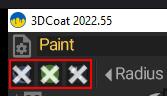
I haven't been able to find anyone else with this problem online, but its not the easiest issue to google, so maybe its not just me. Anyone have any ideas?The only way that I can replicate the behaviour you're describing is by disabling all 3 channels (Colour, Depth & Glossiness) before trying to use the Fill tool, which renders all but the Freeze option ineffective. The icons tend to change location depending on which tool you have selected but in my UI they're located under the Rooms dropdown menu when the Fill tool is selected.
Apologies if this seems like a really obvious solution and is something you've already tried, but as I said it's the only way I've found (so far) to replicate the issue and it's usually one of the first things I check when a tool mysteriously stops working correctly.
-
1
-
-
On 1/4/2023 at 4:42 AM, lechefski said:

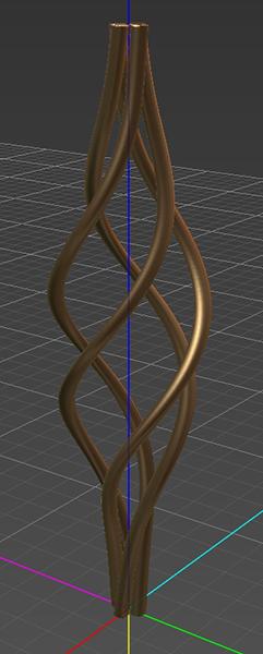
Heyo! Do any of you know how to make these types of twists in 3DC?
For twisted objects consisting of multiple parts like the ones in the above image you can try using the following method...
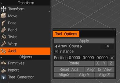
First create one piece of the object and offset it from the center of the scene then go to the Axial tool (in the Transform section of the tools panel) and set up the number of additional parts you want and the position and orientation of the axis along which to generate the copies, remember to enable the Instance option...
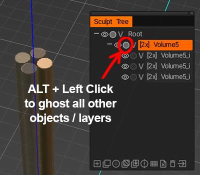
Once you've applied the Axial tool you may find it helpful to ghost the newly created layers in order to make it easier to work on the original object, you can do this by ALT+left-clicking the ghost icon on the parent object layer
Having done that you can use the Move tool (also located in the Transform section of the tools panel) to add the required amount of gap between the objects. Since all the other objects are instances of the object you are working on any changes you make will affect all copies of the object.
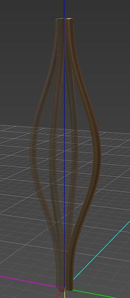
Finally, use the Twist tool (again located in the Transform section of the tools panel) to add the desired amount of twist to the object(s)...
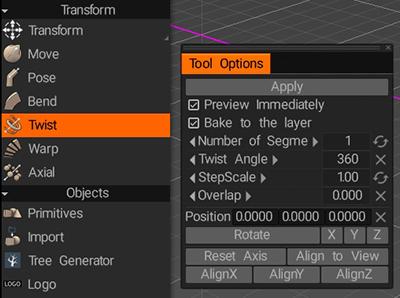
at which point you should end up with a result similar to this...
-
1
-
1
-
-
1 hour ago, NLPLP said:
My main objective is hard surface modeling. Isnt voxel mode the preffered method for that kind of workflow?
That's actually a tough question and the short answer is it depends on how hard you want your hard surfaces.
Technically I'd say the opposite is true and that Voxels are better for organic modelling and the initial blocking out phase while Surface mode is better for hard surface modelling since it's a lot easier to retain hard edges while manipulating your model BUT...
There are a variety of tools and methods you can use in Voxel mode which, as long as you keep your voxel layer at a reasonably high resolution and avoid operations that apply automatic smoothing, will allow you to create some pretty nice hard surface models using voxels.
If you want to do hard surface modelling in 3D Coat I'd highly recommend checking out this awesome series of tutorials by Anton Tenitsky.
Personally I've tried using voxels only, surface mode only and a combination of both and couldn't really advise you on which works best beyond saying that it depends entirely on which workflow you prefer along with the usual factors like what you intend to use the finished piece for. I'd recommend experimenting with various techniques and workflows to find what works best for you, basically just have fun with it and explore the software for a while.
-
1
-
-
44 minutes ago, NLPLP said:
OK great thanks that helped.
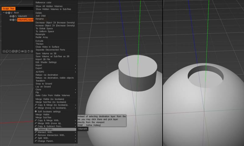
When using the fill with Mesh Layer, if I convert to Voxels (or Multires in surface mode) I loose my sharp edges. Is there a way to maintain sharp edges when using this method? Also is there a way to booleanthose 2 voxel layers in the screenshot (subtract small from the large one)?
If you want to swap to Voxels you may need to increase the resolution of the voxel layer in order to retain sharp edges or fine detail. Keep in mind that increasing the resolution of a voxel layer increases the resolution of the entire object so you can end up with a lot of polygons on screen when working with large objects.
I normally try to perform boolean operations in Voxel mode since they're usually more reliable but if you want to retain sharp edges without using very high resolution voxel objects then you can try staying in Surface mode. Either way you can boolean two layers together by right clicking one of the layers and choosing one of the boolean options (Merge With, Subtract From, Intersect With, etc.) then selecting the other layer.
-
27 minutes ago, NLPLP said:
Hey thanks for the reply Fluffy!
Here s the video
How do those curves work with the sphere tool? I can only make it work with the vertex lasso not splines
Also How does he boolean?
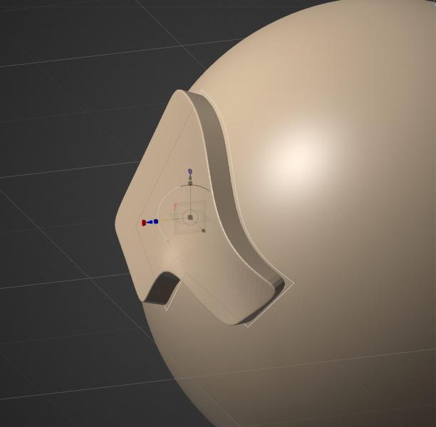
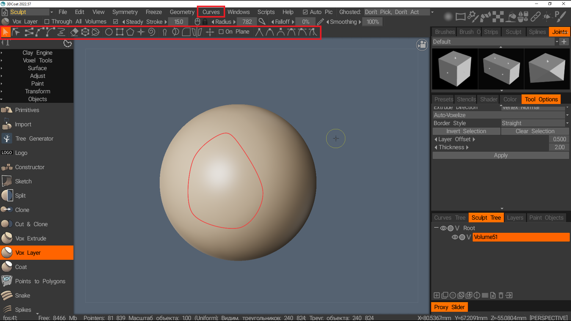
It looks like the method they're using in that video utilizing the Sphere tool is by using it in conjunction with the Fill inside projection option which you can find by right-clicking on the curve in the main window or in the Curves Tree panel.
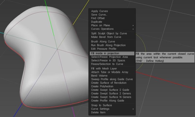
However it looks like they may be using an older version of 3D Coat since the tool options for the Sphere tool are different from the ones in version 2022.55. The object above was instead created using the Blob tool (located directly above the Sphere tool) which still has the Round Border option seen in the video.
Other than using the Blob tool instead of the Sphere tool the process used to create the object in the above image is the same. With your curves loaded switch to Top view and make sure you're using Orthographic projection rather than Perspective then with the Blob tool selected right click the required curve and choose Fill inside projection (the radius of the brush dictates how thick the resulting object will be).
Personally I'd recommend trying an alternative method of using Curves. Instead of choosing Fill inside projection from the menu, try using Fill with Mesh Layer (located further down the same menu) instead. It creates a new layer in surface mode and generates a mesh object based on the selected curve and provides a set of options which allow you to set thickness, mesh density, relaxation, etc. as well as allowing you to choose between flat or round edges or defining your own custom edge shape and allowing you to add holes by creating more curves on a sub-layer of the current curve.
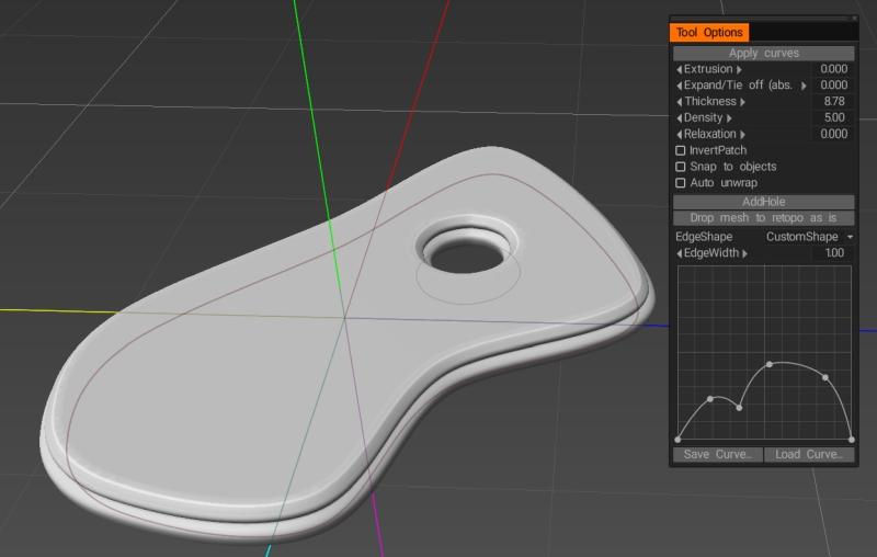
Better yet when using Fill with Mesh Layer the mesh object and the curve remain linked so when you adjust the shape of the curve, the custom edge shape or various other settings used to create the object, those changes are automatically applied to the object until such time as you choose to unlink them.
-
2
-


Learning version
in General 3DCoat
Posted
Thanks Carlosan, I sent an email to sales@3dcoat.com concerning the issue.
I checked the 1-Year rent option however I'm not seeing an upgrade option and according to the License Upgrades Policy I should be able to renew my license for 45 Euros.
Currently the only option I'm given is to rent an entirely new license for €149.85.