


Creator
-
Posts
84 -
Joined
-
Last visited
Content Type
Forums
Calendar
Gallery
Posts posted by Creator
-
-
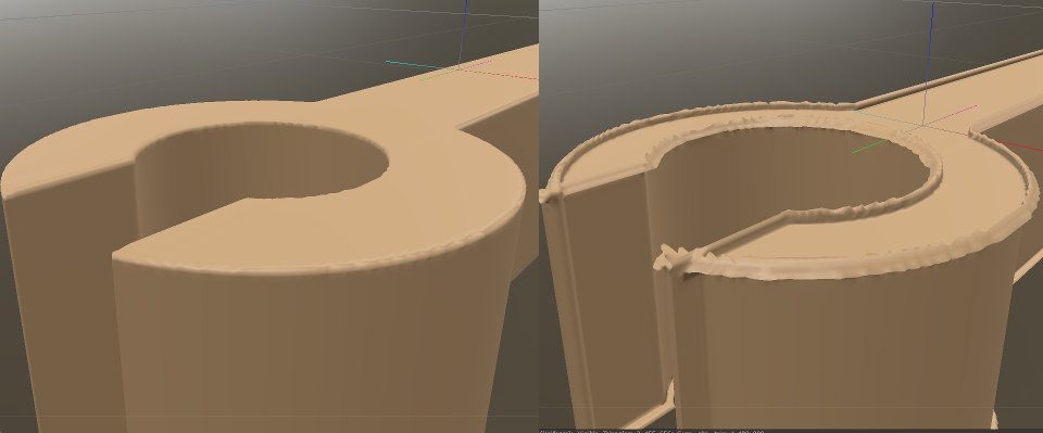
As I said I tried negative values, but it looks like this:
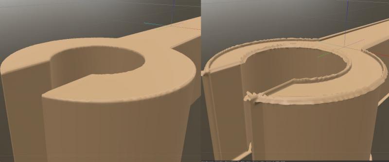
I know why it's happening, normals are getting crossed. It will happen in every 3D app, when you revert extrusion. I think I saw deflate in some 3D app that take care of all faces and normals to not intersect or cross each other. I think 3D Coat should be able to do this too
")
-
Hey!
During last months I'm using 3D Coat mostly for 3D printing, which seems to be the best tool for fast prototyping and merging stuff.
Unfortunately my printer is NOT the top quality device. When I create accurate models it always adds 0,15mm of material to each side.
It happens because it's hard to keep proper thickness of heated plastic pouring from the nozzle.
Now... my solution is to create stuff with dimensions lowered by 0,15mm on each side and it works, but I would prefer to:- design proper dimensions (so i can reuse it in better printers later);
- save file;
- shrink all walls on normals directions by 0,15mm;
- export to STL;
- be happy with proper print;
There is Extrude option that "inflates" object. I've tried Extrude with negative values but it creates ugly geometry.
One of the silly workarounds is to Subtract component in a cube, creating something like a mold. Then extruding it by amount you want and subtracting our "mold" from another cube.
This way you get thinner model in every place.Is there any tool that can do something like inverted-extrude?
-
Hello!
How are new versions of 3D Coat? I haven't updated for a while. I'm just curious if there are any showstoppers or very annoying bugs?
-
I'm learning more C++ lately and hoping to expand 3DC in a lot of ways
Guys, prepare for poorly optimized extensions

-
easy ,...export object along with texture in .obj (.mlt file needs to be there as well I think)
Then Import for Vertex painting from start up choices or file menu....3Dcoat will automatically bake texture to vertex on import
.(I assume you are aware of how much polys you'll need to preserve texture original details)
..then export as .obj or .ply. Vertex paint data will be in file.
Thanks! I'll try this. I just need to fake AO on some mobile models. I can't do it with texture because of app size restrictions.
Have you guys actually tried this?
I can't seem to get the vertex color info to be included in the OBJ or FBX formats. It only seems to be included in the .PLY file, and that only opens in Blender, because Blender is the only one which natively supports .PLY. The OBJs and FBX files import into Maya fine, you can see the mesh in the viewport, but the vertex color info seems to be gone. I tried switching to Viewport 2.0 in Maya and still get nothing. It seems like you can only generate vertex color within Maya, but you can't import it from 3D-Coat... Maybe I am missing a step?
Maya by default is not displaying Vertex Color. In "polygons" mode select object, go to Color and click "Toggle Display Colors Attribute". Additionally in Color menu you'll find "Color Set Editor" where you can create and edit object's vertex color sets. (more info: http://knowledge.autodesk.com/support/maya-lt/learn-explore/caas/CloudHelp/cloudhelp/2015/ENU/MayaLT/files/Coloring-polygons-Make-vertex-colors-visible-htm.html)
-
 3
3
-
-
Hi folks,
Is there some way to bake texture into vertex color and export model with vertex color information?Now I'm using Maya + Turtle, but i'm looking for some alternatives.
-
I think the best name could be "PBR Sets"
I like this a lot. Coat-something is not so good. It should be short and easy, then it sounds more pro. Not some fancy-pancy hocus pocus name like Super Duper Layered Coat Shader Pack.
Edit:
And it should be not associated with other meaning, so users are not wondering why its named "coat" or "sock" or "elephant" etc.
-
Ok.... I have sought of got a decent normal bake of my head,though with A few anomalies I will suffer through... but now everything else has a reversed normal map?? ,after I made the blending mode -1 for the head . I think I will just have to paint things separately for this one ,which is not the perfect solution.
Separate head UV from other parts (i mean UV sets, not UV groups) and before baking of other parts export head normal map texture to file. Delete Normal map layer and bake other parts, afterwards import head texture . Should work.
-
I wonder if any one can help me with this, I have not a clue how to fix this. The normal map is reversed after I merged to normal map? It is likely a setting is wrong, but other parts of the same model seem to work ok. Could the sculpt be "broken" I have used a retopo mesh done by hand in Coat and also imported a mesh for retopo from zbrush...same result.
Fast walk-around is to set Depth Modulator to -1 in Blending tab of normalmap Layer. Hard to say what happened in your case. You're importing this normal map or bakeing it from Voxel?
-
1
-
-
Hi
I found workaround for this problem.
1) Import Obj file for example to Paint room (File=>Import=>Model For Per Pixel Painting);
2) Go to Retopo Room and click "Use curent low-poly mesh" under Retopo tab i Menu Bar.3) Switch to other room for the moment and go back to Retopo Room, to refresh UVs (it won't refresh from some reason).
Problem is that importing model to Paint room forces you to create new scene... (If i'm wrong, please correct me)
So you need to merge your sculpt scene to scene with prepared model in retopo room. -
Hi,
I've mirrored 3dcoat installer http://78.47.23.219/tmp/3dcoat/ to my server which is in idle state right now.
So during the time when i'm not using it for other purposes feel free to download from it.-
1
-
-
I'm not posting screenshot, but tested your scene and there are still jagged edges. The workaround is to bake higher texture resolution (for ex. 4k) and scale it in ps/gimp to lower resolution.
-
1
-
-
So far on my past experience, I plan to, like you said, start an aggressive testing session sometime in the week, but I don't know when, I've hardly enough time to sculpt for the challenge lately... (the last sculpt was a test of stability for the latest build).
Maybe it got better, I hope so, still those brushes which feel very poor...
Make Live Stream while you "aggressive testing"
I want to watch those tests  (I hope i don't sound like a little pervert ;D)
 -
- Scripting got major update. Look documentation. Generally it allows to do non-destructive modeling with primitives. It is good to create parametric hardsurface stuff. Scripts may be inserted in any top menu section. Paint layers management via script introduced. Extended control over voxel scene allowed.
Nice !!
-
To uniform space in current volume:
cmd("$ToUniformSpace");/*To uniform space*/
And rule:
Any RMB item accessible through same rule via RMB+MMB (copy item to clipboard)
Yeah I know, but it doesn't worked for me while i clicked RMB at Vox Layer and then RMB + MMB at "To uniform space".
-
Hey !!
1)
Have no idea how to run "to uniform" via script

2)
Only option is to choose:
SelectFirstVolume(false); // false - if you want to select visible and nonvisible layersThan you can select next layers in a loop with:SelectNextVolume(false); // false - if you want to select visible and nonvisible layers -
You can remove voids in surface mode by executing "Separate disconnected pieces". It will separate all not-connected surfaces to layers. Then you delete unneeded layers. Problem appears when it generated more than 50 layers
Then it can be time-consuming task. -
Is there a way in retopo room that when you ctrl d or deselect, it does not go to auto? Its really breaking the modelling flow when you're selecting in poly mode, then deselect it goes to auto mode.
You can force it via script, but if won't work with Ctrl + D, only by pressing button.
-
Everything is working fine. Version Win 4.0.09 OpenGL CUDA. It by using a memory with a character in a T-pose of not more than 5 GB with 5.5 million polygon. Config: i7 3930K 3.2 GHz(4.1), Kingston SSDNow KC300 240 Gb, Corsair XMS3 1600\32Gb,Gigabyte GV-N780OC
After switching to voxel from raw LiveClay sculpt (~5 milion) split works super fast. Then from Voxel to Surface and split works fine, but slower. Still can't split from raw LiveClay sculpt, it crash.
Edit:
Ok i figured out, that it only crash when i split character in half. When i split smaller parts (for ex. foot) it works, but still uses too much memory in my opinion.
-
On a simple object, yes it works, but when I try to split character model in a T-pose (~2.5 milion polys), it increase memory from 1 GB to 11GB (11 times !!). Then 3D Coat crash because of lack of RAM (i have 12GB here at home). I'll try at Monday on the machine at work, it has 32GB and we'll find out if it will end process or fail. But hey, 11Gigs from 1 is just unbelievable!!
-
-
Except for some very seriously improved performance over Win 7. I was hesitant to jump on Win 8, but, to quote you, I haven't looked back.
Win 8, in spite of Metro interface, is better, faster, stronger than win7. I really appreciate it.
-
Ok i've exported normal map, imported it to new scene and smoothed diagonal lines with brush. That's only solution i found. Not cool
-
Creator,
The normals issues you're getting look like they're related to how one would triangulate the quads. I realize you probably had nothing to do with that and the quads are still there, but artifacts like that tend to appear when the angle of a triangulation is in the wrong direction. The input about the brushes makes more sense to me, in this case.
So whats the plan ?
 How to get rid of it?
[Solved] Opposite action to extrude
in 3D Printing
Posted
Ok I found better workaround:
Anyway it would be cool to have such functionality on one action