

DMG
-
Posts
91 -
Joined
-
Last visited
Content Type
Forums
Calendar
Gallery
Posts posted by DMG
-
-
Thanks Andrew.
I tried that, but it didn't work. Then I remembered I'd relocated all 3DCoat's data to a folder on my D: drive. Pointed it to that, and and everything is back where it belongs.
Thanks,
Derek
-
 1
1
-
-
Just a quick upgrade related question...
I've just updated to 2024.13 and have lost all my keyboard shortcuts, grid settings, panel arrangements, custom brushes, sculp object folders, etc...
Is there a simple way to use the settings I had? Or do I have to reload and reset everything manually?
When uploading, I did get a message saying that because of a conflict or incompatability with onedrive, lots of config stuff was being moved to (I think) my user folder. I didn't really pay too much attention to the details of the message...
Cheers, Derek
-
Nice try Carlosan. I thought that might be it. But it turns out I already had Aces turned off.
Thanks for making the suggestion though. Reassuring to know this hasn't been forgotten.
Aha! I think I've just solved it. The scene lighting was also affecting the MatCap. I turned the lighting contrast right down to zero, and set the scene lighting to 75, and it's a near-perfect match. Brilliant.

-
Hi Oleg,
That looks really promising. I like how if polygons are selected, it seems that only those will snap/weld.
I can follow that: Create geometry; apply symmetry; move geometry so it overlaps; each side is still separate parts.
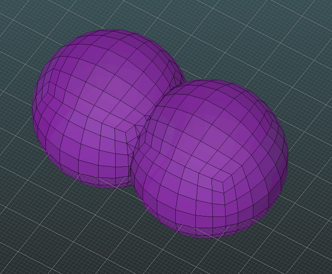
I think the last part which is niggling me is that if I have two spheres overlapping (as in my example above), after deselecting it, and then reselecting the polygons, when I try to move it, the parts which are on the 'wrong' side of the symmetry line don't translate the same as those on the 'right' side of the symmetry line. I have to turn off symmetry to adjust the position, but obviously, this is only going to affect one side. But this seems to be the normal behaviour for geometry which crosses over the plane of symmetry.
Not perfect, but close enough to call a solution.
")
Thank you.
-
Hi Oleg,
Thanks. that might help in some circumstances.
The problem I had yesterday was for a pair of eyes which I wanted mirrored—but with overlap—so I could continue to adjust the separation. This wasn't possible with the points automatically welding every time I stopped moving them.
I ended up using virtual mirror to get it about right, then unlinked the subdivided sculpt mesh, before mirroring it in the Sculpt workspace.
Cheers Derek
-
HI,
Am resurrecting this old thread because I'm wondering the same thing. I have an object (in the Modeller Room) which has geometry crossing the 'x' centre line, and I'd like to mirror it without any points automatically welding together as I will be adjusting it later.
Thoughts..?
Cheers
**EDIT... I've just discovered 'Mesh: Virtual Mirror Mode'. That seems to do what I need, but it doesn't appear to work in conjunction with Live Smooth, so a subdivided version of the mirrored object isn't visible in the Sculpt Room.
-
 1
1
-
-
Hi Carlosan,
Yeah, I tried that. It adjusts the tint, and helps get the lighter areas close, but it doesn't lighten the darker areas.
It's the best option so far, but I'd still prefer a way to use the MatCap exactly as it was created.
Cheers, Derek
**EDIT** In case anyone is wondering why I'm being so particular, that MatCap is what I use to render projects for clients when I create a PDF with orthographic images and specifications. I'd like to be able to render or screen-grab from either Blender or 3DCoat and have the result be indistinguishable.
-
1
-
-
Hi Carlosan,
Thanks for the suggestion, but I've switched to a few different HDRI panoramas, and they don't make any noticeable difference. The thumbnail in the shader panel also has much brighter highlights compared to my original MatCap too..
Regards,
Derek
-
Hi,
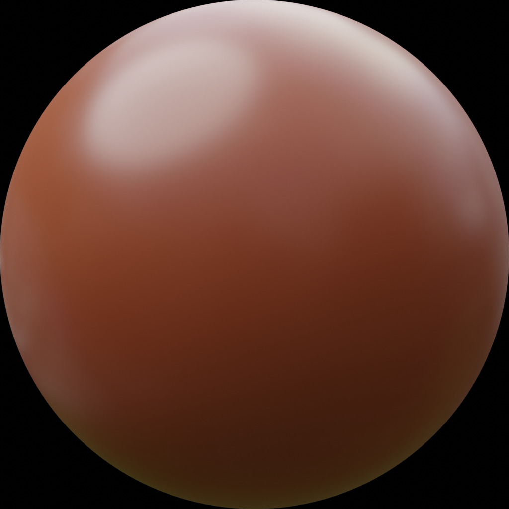
I'm trying to use a MatCap in 3DCoat, which I also use in Blender, and I'd like them to match.
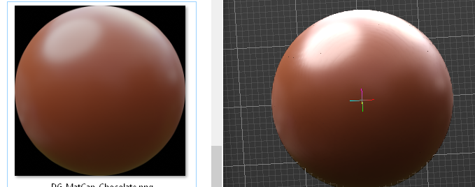
I'm using it in the sculpt room, and creating a simple MatCap shader to use it with. However, once loaded into 3DCoat, it appears that the RGB values of the MatCap are being 'normalised', as the light patches become much brighter than they are supposed to be, and the darker areas become noticeably darker.
Left is the original image, Right is it applied in 3DCoat.
How can I get the shader in 3DCoat to match my image? Am I overlooking an option somewhere?
Cheers,
Derek
-
I think I may have found an 'undocumented feature'.
 Something I've been looking for the ability to do for ages.
I often want to move multiple polygons outward, with each vertex moving in or out, along their individual normal.
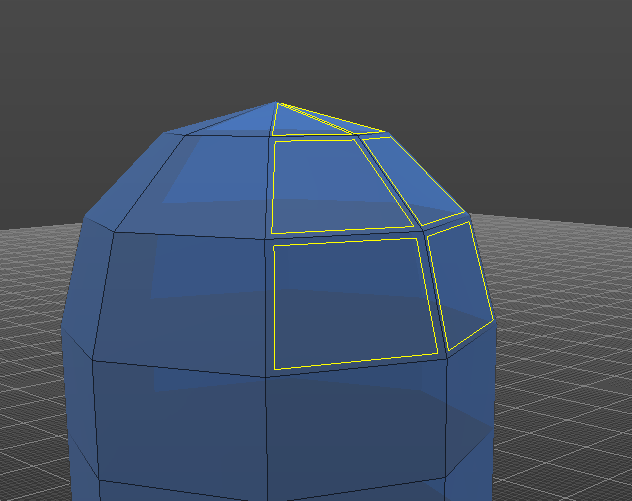
The Extrude Vertices tool moves the polygons outwards in the manner I wanted, but I often don't want the extrusion part.
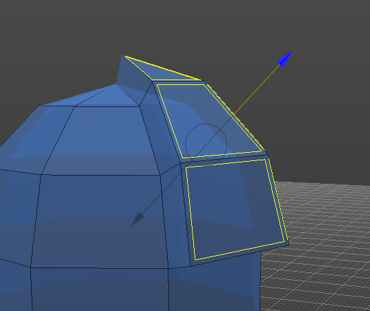
I have just accidentally discovered that if, after using the Extrude Vertices tool as in the above pic, but then without dropping the tool, do CTRL+Z a couple of times.
The first CTRL+Z moves the geometry back to it's starting position. The second CTRL+Z undoes the extrusion 3DCoat is performing.
Now, you can continue using the tool, and it only moves the selected geometry without the extrusion.
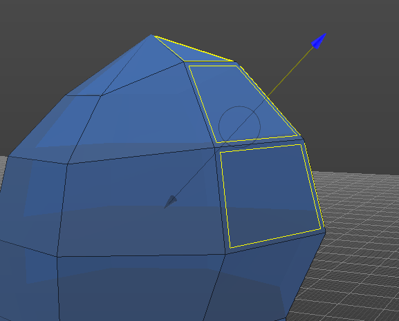
I'd like to think this behaviour is on purpose. If not, please don't 'fix' it! My personal preference however, would be to have a check-box in the tool options to allow users to decide if they want the extrusion or not.
Cheers, Derek
-
 1
1
-
1
-
-
Ahhh! I'd completely overlooked the Tool options, and was just going by the tooltip on the left-hand tool menu.
Most other software with a Knife tool has very 'focused' functionality that just cuts lines that you draw out. That polygon generation option in 3DCoat is brilliant.
Thanks Gorbatovsky.
-
1
-
1
-
-
Hi, I have a quick question about the Knife tool.
I understand the basic functionality as clearly shown in the video Carlosan posted above, but the tooltip and documentation says "Also, you can draw a polygon by two points."
Maybe something is being lost in translation, but that sounds to me like there's a bit of extra functionality that I haven't figured out yet. Can anyone elaborate?
Cheers, Derek
-
Perfect!
Have never noticed that wee padlock before!
Thank you, exactly what I was needing.
-
1
-
-
Ah, sorry, I'm working in Sculpt room in voxel mode, not Paint room.
When I said 'texture' I probably should have said 'brush'.
(But that's a good tip anyway)
-
HI,
I have a texture I need to apply to a model as a stamp (a scaly skin for a dino) and am applying it using the stamp tool, with some areas scaled larger than others. It will be produced on a CNC machine, so I am working in a 'top down' view, and applying the texture by 'view direction'.
The thing I'd like to avoid is that it is also scaling the depth of the stamp by the same amount as the horizontal scale, but I really want the depth of each to be consistent.
I know I can adjust and vary the depth before each (eg if I'm applying the stamp about half the size of the previous one, I can double the 'depth'), but I'm having to guess and eyeball, when I 'd really like to have the depth consistent.
Any suggestions?
Cheers,
Derek
-
12 hours ago, Elemeno said:
but at the same time .. whatever you make with them tools .. you could do it faster using the cut off tools or booleans ..,
Mostly. I needed to make a handle with changing profiles yesterday, and I the Sweep with multiple generators would have been the best/fastest way to do it whilst retaining control over the shape, and being able to modify it until I was satisfied. Except it wasn't the fastest, because it didn't work.
-
13 hours ago, Gorbatovsky said:
Unfortunately, this tool turned out to be inconvenient to use and needs to be improved.
That's a shame. I think it has great potential, and if there was some way of getting the functionality from the Modelling room across to Sculpt, that'd be great.
-
Yeah, it seems like it should be simple or obvious, but isn't.
I can't get the "Add Loop Direction Line" to do anything either (other than show a magenta ball when I click on a curve). I'm guessing there's some secret combination of right-click or middle-click or something which unlocks the rest of the functionality.
")
-
I think the title pretty much asks my question.
In the sculpt room, I can create two curves to use as guides, then select two curves as profiles. But the tooltip and manual suggest that 'N' number of curves can be used as profiles and I can't see where or how to add more than two.
Cheers,
Derek
-
On 8/21/2023 at 10:19 PM, VitalVolokh said:
Ok. Thanks for the system information.
Can you run "nvidia-smi --query-gpu=compute_cap --format=csv" from command line to get the compute capability?HI,
Thanks.
I ran this, and received the result:
compute_cap
6.1I have an nVidia1050 card in my laptop.
When running the photogrammetry Room I get the message:
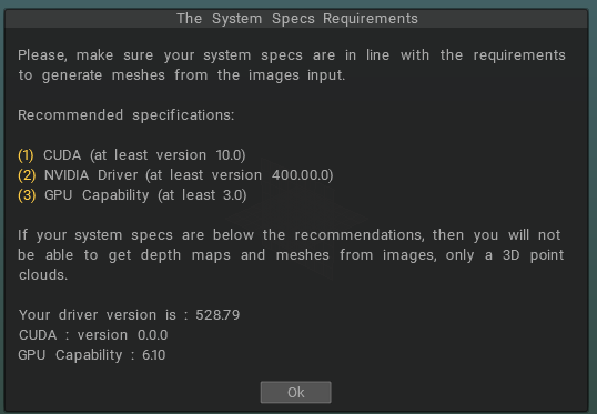
CUDA being zero seems like it might be an issue.
Cheers,
Derek
-
My experience was the same as kenmo...
I normally use 3DZephyr for photogrammetry too. In 3DCoat I managed to get a point cloud, but couldn't see any way to progress.
-
1
-
-
1 hour ago, Andrew Shpagin said:
What you tell is Bas-relief!
Ha ha.
Now I feel really dumb. I thought 'Undercuts' had behaved like that in the past, and then changed. I must have used bas-relief at some point before it ended up in my blind spot.
Thanks for pointing out the obvious!
Derek
-
There is an option that I would find incredibly useful in the Undercuts tool: My work involves creating moulds which will be milled on a CNC machine, so the top will be sculpted/detailed, but the bottom needs to be flat.
The Undercuts tool at the moment (unless I'm missing something) only seems to create two sides of a mould. If the initial object has vertical sides, then draft angles are created from both top and bottom, and meet halfway up. If there was an option to only create draft angles from the top, and fill in the object so that the base is flat, that would be great.
At the moment, I have to do extra work to make the Undercut tool do what I need.
Derek
-
Just checking this is an intentional change in behaviour... (I'm on 2023.25)
When I use Pick & Paste, the red target doesn't centre on my cursor, but the closest edge of the target circle does. Tool otherwise works exactly as expected.
Derek
-
1
-
3DCoat 2024 development thread
in New Releases, Bugs Reports & Development Discussion
Posted
I was trying the same thing today. I just copied the red, green and blue channels individually to the mask channel and it worked fine. I suppose the mask should just be a single B&W channel, but it works. But being able to copy all three channels at the same time would save some clicking.
It would also be good if there was a function to select a non mask layer, and make it a mask of a different layer. But I suppose this is just a 'same but different' approach to copying another layer to a mask layer.