


Jax_Cavalera
-
Posts
97 -
Joined
-
Last visited
Content Type
Forums
Calendar
Gallery
Posts posted by Jax_Cavalera
-
-
I have created a video that shows my latest progress thank you to all your help to get me this far. If anyone is able to point out where I can improve to get a problem free Bake of my mesh with 3D Coat I would be really appreciative.
The video at the time of posting this still has 270 minutes remaining before it has completed the upload process and is available to view inside this post just as a heads up.
-
Oh cool, so the toes aren't normally meant to be spread apart like that. I did suspect this may have been the case but wasn't sure so I thought I would try to do them as shown in case. That's one less problem now. Just the remaining artifacts.
I did notice that in areas on the hand, when I deleted the existing topology and then replaced it with slightly different arrangements that the artifacts in the replaced zones was fixed so I'm left to assume that it is probably caused by the poles I have on the palm of my retopo mesh's hand.. or was.. though it's also happening around the sides of the hand too and there aren't any poles on the top of the hand so i'm still not exactly sure what needs to change there to make that all better.
I am getting a lot closer though now.
-
Hi, thank you for this information, I have tried it with the setting of no subdivision and it comes out with no claws which was one of the issues I received using the subdivision level so that's good though the other complications with the holes / artifacts in the hand and feet are not resolved.
I did fix the shoulder seam issue by taking the mesh back into voxel mode.. smoothing and filling holes etc then taking it back into retopo room so that's another positive so far.
just those other 2 issues now and it's all sorted ~~
-
What i've tried since the previous post is to turn on snapping again so that the retopo mesh sticks to the reference mesh as this is typically the way I've seen other's work and I was trying to get a better result by producing a larger "shell" but this didn't work. I also was not able to find a quick way to simply expand the retopo mesh so that it extruded away from the reference mesh by a set distance uniform. something like that would save a lot of hours I spent looking for small parts of the ref mesh sticking out through my retopo mesh.
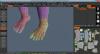
Anyhow.. what I have attached is the before in process and after of trying to get the feet to play nice for Baking with snap back on this time.
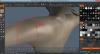
In picture 1 it shows the mesh as expected pre bake
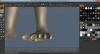
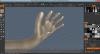
Picture 2 shows how the mesh looks when I try to set the outer depth.. lots of intersecting which I can NOT get rid of without the outer depth not properly extruding out beyond the surface of the reference mesh. I'm lost for inspiration on how to fix this as it will look so wrong if I move the toes apart much further and the retopo mesh is a tight squeeze without any increased depth beyond 1.5 when I tried to manually sort it out... and with this setting it overlaps way too much .. not sure if that is a problem or not though... can't imagine why it won't cause issues.
What do you pro users normally do for that kind of situation? do you do all the foot as a single area and not worry about going in between toes?
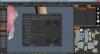
I've tried going with 20 for the occlusion depth so i'm not sure if that's another cause as occlusion wasn't mentioned in the happy baking pdf that I saw.
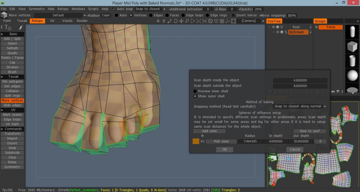
Pic 3 shows the settings I use for the norm bake.
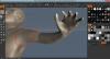
the other pictures are more about the results. and they also show that odd seam around the shoulder area I was trying to mention earlier as well.

-
I have no idea where my attempt at a post vanished to but it's "charged" me 1 post for the day so it will likely show up some time but is not currently showing up.
Anyways on topic, I am having a different looking type of glitch show up and in unexpected areas where there was no conflict between baked inner and outer layers. It also messes up in the Occlusion layer etc so I'm not entirely sure what the cause would be for this.
any tips would be appreciated. I do intend to look through the happy baking guide, am just wanting to see if there is an obvious cause to you veteran bakers out there.
I also notice there are extra layers there and I've no idea what they are for.. I get the layer for the occlusion, normal map and base mesh.. and I'm guessing another layer is for my subdivided mesh though am not sure which.
I'm also unsure as to which layer I am meant to be painting onto if I'm wanting to just paint the texture for my character. At a guess I do not touch the occlusion or normal map layers unless I want to paint in extra normal map or occlusion information.
p.s. sorry Digman I swear I was paying attention when you showed me this stuff.. I just have a rubbish memory or something and don't remember all these extra layers showing up before or the glitching happening on that sphere example.
p.p.s I've read that guide through now for the happy baking and my baking is still not happy. It doesn't really cover or show the 2 problems I get.
1. Holes in my baked normals and occlusion map.
2. Artifacts in the Baked normals and Occlusions
Now I am guessing holes appear when the inner depth protrudes outside of your reference mesh or your outer depth does not fully cover the reference mesh. OR inner depth and outer depth intersect somehow.
Is it normally this hard to get a simple normal bake to work on a standard biped mesh you sculpted or is it just bad luck I'm having here?
-
Just checking... I honestly do not have a working understanding of what AO is used for though in this situation for 3D Coat.. if I'm baking the normals etc.. using the NM option from the Retopo menu. What is a good distance setting for a Biped game character and is this now an improved setting in V4 as I note this discussion is a few years old yet seems to be a well targeted topic towards the questions I have.
Am just wanting to determine if 3D Coat is now a good option for this feature or if I need to still go outside of 3D Coat for this and also to determine if AO is needed for Game Characters.
-
The way it appears to function is that it is actually maintaining the vector nodes and curve information and then it starts off with a base smoothing value of 1. As you increase this value, it increases the polygon count so that it can better fill out the vector curves which produces a far superior result with more precise mapping of the vector curves to the point where the human eye would not be able to distinguish between the vector original and the polygon duplicate at extreme close-up inspection.
To this extent I am lead to believe that your analysis of how this import script within blender works to be in-accurate. It's not working on the same principles at all when compared to the import of a raster file format within 3D Coat.
The process you describe is doing as you explain within 3D coat for a raster image where there are no solid vector curves for the shape to map within the confines of and hence produces a "smoother version" of the original raster image.
Vector file formats such as EPS, SVG, AI and CDR are also able to be exported as DXF files which of cause are 3D Cad file formats. The only difference between a standard mesh and one obtained via a vector file is that the vector shapes when closed are essentially N-Gons ... the script then simply needs to determine how many subdivisions (smoothing) are required to break the N-Gons down so that they form polygons which can then be better extruded and handled in 3D modelling software as non-planes. If N-Gons were able to contain curved lines between vertices (nodes) then this would allow for instant importation, however this is not the case and that is why it needs to perform the subdivision process to represent the curve.
The key point to note is that during the entire process, the image vector information is not discarded and is instead used for pin-point mapping and conversion.
As far as time required to perform this sharper conversion from vector design to polygon plane goes, it is questionable that the process takes longer to perform. It does require an extra program as the import of vector within 3D Coat is currently not a supported feature though actual time-wise is quite swift and painless.
I hope that this better explains the advantages of using the Vector designs with this process. Of cause as neither of us were responsible for writing the import script it is still conjecture as to which explanation fits the process taking place in both situations better.
"
-
 1
1
-
-
Hi Jigsaw,
Thank you for providing an extra method to be used. I'm sure that will be helpful for a lot of people who are not as concerned with using this for professional graphic design work. To answer your question though, yes I did try the method you describe to import the design in.
There is a critical problem to consider which deterred me from using this method as hinted above and explained below.
The design is vector from the start which means it is able to be scaled to any size without loss of quality on edges and is also the most accurate and sharp representation of the design possible to achieve. The method you describe will work fine for a bit of fun but for anything professional, you will want to maintain the vector format's quality and integrity.
I agree that the other method you show will produce good enough results for the casual usage in say a game, but for professional logo presentations you would definitely want to have the exact pin-point sharp edges and smooth curve lines transported from the vector image to the 3D extrusion.
It's something that I saw happen quite often during my more avid graphic design years in the online industry. A designer would produce their client's design using a method that saw minimal quality reduction and then another designer would use software that was able to produce identical conversion from vector to polygons. The designs would often be very similar and yet the design that looked sharper in the 3D previews often came out in front.
The online graphic design industry is a highly competitive field and any slight advantages you can find to get a foot up over the competition will definitely be worth the effort.
I agree that the process I demonstrate is not the most efficient as it would be far more practical to simply import your SVG or EPS or AI or CDR file right into 3D Coat and then perform a simple extrusion with crisp results. It has been mentioned that the shaders I used in 3D Coat have been the cause of the poor representation due to the wireframe showing all curves as they were seen correctly displayed in Blender.
It's unfortunate that the shaders I used would typically be the most popular for logo presentations and the preferred options to have working correctly in this situation.
-
Hey Digi,
Thanks for looking into this further, I will give the tests you mention a go and see if it improves the quality or performance of the imports and render. Hopefully this workflow can be established as a good work around and perhaps once we isolate exactly where the problems are being generated, we can make a clear feature request/bug report.
-
This is a quick tutorial I have put together to help other graphic designers using 3D Coat, bring their logo work from their design program into 3D Coat.
The advantage of doing this is that you can produce really nice logo proofs for your clients that will provide a higher chance of getting your professional designs selected by clients within the online graphic design industry.
The industry is very cut-throat and any step up you can get could be the one you needed to win more bids on jobs.
Currently, there are a few bugs regarding the importing of these Vector designs into 3D Coat so it would be really nice if those could be smoothed out. It would also be really great if in the future there was direct support for importing SVG, AI or EPS file formats. For me personally CDR file format compatibility would be ideal though I'm fine exporting to more standard formats.
It would be really neat if the front surfaces were constructed using larger polygons such as ngons so that they provided a smooth reflection though if the shader issues are fixed they will look great either way.
Anyways, to those graphic designers out there that have wanted to do this, here is a video tutorial.. hope you are able to follow what I do and any questions, please feel free to ask below and I'll do my best to assist.
The video will take a bit to upload due to our limited internet speed here in Australia. At the time of posting this, the video is at 15% uploaded.
-
1
-
-
Wow thank you that's a very detailed and clear explanation which makes a lot of sense.
-
Hey guys, these tips are invaluable and really appreciated. I wasn't 100% sure if I should be trying to get a seam down the side of my model (thinking to unwrap it like an easter-egg cast... OR to have a side set of panels that run down there as essentially the seam would be on the character's back.
Have any other members here experienced the problem of that crease (extra messy topology) around the symmetry line?
If I push vertices together so it looks like a solid line in the middle it seems ok, and yet I am still able to use a brush to pull them apart and it's like a never ending supply of vertices that jump out of that symmetry line. pushing excess into that line might cause problems later on though I am not sure.. or would the symmetry destroy anything at that edge to leave you with 1 crisp middle loop/seam?
This has been a problem experienced in both Autopy and Manual Retopology.
-
OH yeah I forgot that you can use those 2 in combo outside of Autopy like that. Then they work the same as the contour tool from blender I mentioned. That's cool. will give that a go and see what can be done. I think that the work I achieved with Autopy in the OP is likely as good as Autopy gets so this is currently the end of line for this thread until we get to see the next set of upgrades to the Autopy tool but I'm happy if others have extra to add.
-
Hi Abn, thank you for this extra information. I know what a spiraling edge loop looks like. I re-watched the video again and can't find where I was referring to normal topology as spiraling edge loops as each time I noted them, they were spiraling to the best of my knowledge.
I agree that trying to use automated scripts such as Autopo to do ALL the work is a bad idea. The way the script works, you end up spending a great deal of time laying down the ground work for it before it can even work it's "magic".
Personally I have found manual retopology to be too slow and inefficient on it's own. I tried using box shapes to kick start the manual topology process as an alternative and this produced the same issue I started to see popping up with Autopo.
I might end up using Blender to kick start my topology and then moving the mesh into 3D Coat as it has a superior kick-starter technique to lay down the cylindrical topology shapes quickly called Contour. It is a free add-on for blender though the creator is looking for donations to support it's expanded development. I can definitely see using that tool to produce arm, fingers, toes, torso, feet and neck topology as a benefit. Then you just have to join the pieces together and create "caps" for the fingertips etc. I would probably drop a sphere over the head of the mesh and conform geometry using the brush smooth tool for the head and cut out the face to re-topo that part manually for more precise looping.
However that's a hybrid solution so I'm keen to see if we can find a superior solution exclusive to 3D Coat as it can be a pain jumping from one program to another.
You end up with this messy topography at the symmetry seam line. I'm yet to fully understand what causes this to happen but it has produced everything from mesh gaps to triangles that break what should have been healthy edge loops.
I can't stress enough that the goal here is not to stay with the existing workflow and painfully chip away at manual retopology but to try and find ways to generate faster clean topology. There are no expectations of what these tools should do, only excitement over what we are able to achieve with them. I don't really see the danger in trying to find a faster way to use software so that it unlocks and even faster workflow.
The best results I have achieved so far are using a combination of different things.
I will edit the opening post with some new information that has become apparent thus far in the topic.
EDIT :
Never mind forgot that you can't edit older posts for some reason.
NEW INFORMATION
The Red/Orange rings produce spirals when they are not being intersected by 2 Green strokes.
When I used more than 2 Green strokes to intersect a Ring it would cause spiraling unpredictably (not on every loop but most)
Working with sliced models provided me with a lot more control over Autopy which resulted in faster workflow.
I was not able to achieve a clean set of fingers or toes with Autopy and therefore am considering either manual retopology or slicing them off and Autopy on their own. I think at this point manual retopology would be faster using quads direct/2 clicks mode.
-
Hmm I have tried that before and it simply created spiral loops for me. Will give it another try though. I'm also experimenting trying to achieve a "shrinkwrap" box effect for manual retopology so I add a cube to the retopo room and place my torso inside it.. then start adding split rings to fit it to the shape of the body as desired. So far it's only crashed 3D Coat but I'm hoping to get it working as a possible alternative to Autopo that requires minimal time / effort for good results.
edit. Quick test on the same mesh shown in the above video using Orange/Red rings exclusively shows that they produce spiral loops. I tried using them with green lines and the results are similar except with good edge loops forming every now and then. Without them at all, there are only a handfull of spirals and they are not major elements inside of the topology.
I know this is all in the works to be fixed so I'm not saying that it's a broken tool, just finding a way to use it in it's existing form and sharing that wth others so we all benefit is my goal.
-
Hey yeah no worries, umm it's currently at 75% uploaded so it should be up there soon. After looking at the hand areas further, I would be keen to know how other people would do them differently using manual retopology so I can compare the results and get more clues on how to further guide using density painting.
-
I have started some research as the result of correspondence with another member of the community and we came to realize a few things about the Autopy toolset.
1. Avoid the Orange/Red loops at all costs as they guarantee spiral edge loops.
2. Try to keep all Green Strokes flowing in the same direction for major sections
3. Splitting your model up into pieces can improve the topology results.
Later I was working with these concepts (forgot about the splitting model up one till now) and I came across another interesting thing.
Autopy likes to follow density painted areas.
This started me on some testing and below is a video with the results that are actually pretty good considering. Hope that you all enjoy and are able to help tweak this system even more.
p.s. vid is still uploading if it isn't showing up yet .. it goes for 24 minutes sorry for not clipping down the work.. I personally like to see things from start to end though I know some people prefer to see the start of a few bits of work.. then timelapse and it's all done.
-
Actually your tip about the brush did it. I tried a lot of the brushes but never gave the one I was meant to a shot.. murphy's law. I thought I had the brush tool that looks like the one in the tutorial video selected.. but it turns out that the one I was meant to select was just one brush over to the right and looks similar to the brush I was using so I will put the recording up so others can figure out what to do as well faster in case they are as blind as me!
Thank you all for your help solving the mystery of the blind 3D modeler XD
p.s. PSmith this is correct I was on the wrong brush and was use to Sculptris where Brushes are used to add texture to your sculpting tools not change the shape of how the tools work so that had me thrown a bit there but it's all good we got this sorted. Thanks again everyone for helping get this one taken care of.
I notice at the end of the video some information missing from the top area but couldn't remember the names at the time of the recording : The name is Interpolate so I was right the first time with it starting with an "i" and wrong when I thought it was Extrusion, that extrusion bit comes later on I think when you did the eye sockets as an inverse extrusion.
-
Hi, when I do as you say, it simply makes the brush size larger though the actual tool comes to a point still not a curve as shown in that video. I am going to try and do a Skype session to see if we can determine the cause and if we get it fixed then I can post what to do so others can get their Move tool working from the start.
I will also try to make a quick video showing how it currently functions to better explain the situation as this may be of more use than just textual description.
-
I can't edit the above posts so this is why I'm having to make extra posts here :s
I saw a tutorial that is about making some pervebial pirate thing and the first step in their tutorial is using the Move tool like I tried.. EXCEPT in their video it doesn't come to a point but it's a curve so it can move areas of mesh instead of single points in a mesh. How did they do that I wonder? I guess it would be neat if the tutorials show how to set your HUD up so it looks the same as theirs or they just used the default layout for the software.
-
To help explain what I mean better I have a short video that contains the Grab tool being used and a few other tools I was not able to find an equal or similar option for inside of 3D Coat.
Video is still being uploaded so it may not show instantly but will show once the upload is complete
-
So I decided to give the sculpting tools a shot so that I can fairly compare 3D Coat to my existing workflow to determine if it justifies the cost to purchase and have run into a few problems trying to replicate my previous workflow.
I am wanting to find out how I can achieve the same results I get in Sculptris when I use the Grab tool. I found a tool in 3D Coat called Move, but it only grabs 1 pixel and drags this.. kind of works more like the Pinch tool from Sculptris.
If anyone knows the name/way to use the right tool to achieve the same result please advise.
EDIT
I also have seen a Pointers counter at the bottom of the 3D Coat program and every time my cursor is over my model, it starts to rapidly count down.
It was at -7000 a little ago and is now all the way to -12000.
As this number decreases.. I am seeing my memory getting chewed up. this can't be good right?
DOUBLE EDIT
The larger the brush size the faster it decreases, the smaller the brush size the slower it decreases. I'm not clicking just hovering my cursor over the model with the Move tool selected.
TRIPLE EDIT
Is there a way to change how much detail is added or removed when you are sculpting. In Sculptris I was able to adjust the tessellation level so that it would either work without adding any new polygons or it would add extreme quantities of them. Using this method I was able to control the polycount in areas where high detail was not required. I'm just trying to determine how to achieve this same result inside of 3D Coat.
-
Thank you very much for that info that is a huge help and YES!! the spiraling edge loops are a real pain. That is going to help a lot more in producing good topology. I'll have to give the sculpt tools a try and see how they go.. they sound worth the time to learn enough to test out definitely. I think as long as I start with only Quads and keep only Quads, then I shouldn't end up with any Triangles.
-
Hi and thank you for this information. Do you find that your 3D Coat program crashes if say you do the topology.. then you delete the topology mesh on the right hand side.. then you click on the hi-res mesh again and choose autopo? I thought I'd give that a go but it always crashes :s I guess once you do Autopo once on a hi-res mesh you can't do it again unless you start a new file?
Hmm those extra features do sound handy though most are easy to achieve inside of Sculptris with it's good integration with a pressure sensitive pen. The best feature you highlight is the one that lets you cut into your mesh to make gaps etc.
Do you have the same issues I'm experiencing when you work with your 3D Coat Sculpts or is this just 3D Coat struggling to work with imported Obj files?


Some of the UV Islands in a symmetric model are asymmetrical
in General 3DCoat
Posted
hmm the first thing I would check is whilst in the Retopo room, look to see if down the bottom it says Perfect Symmetry. Often and I don't know the cause but it can get out of synch from left side to right side even slightly with symmetry turned on so it might have done this. I miss it all the time as I don't expect a mesh with symmetry on to stop randomly replicating each alteration I do.
I'll note that tip down as well Abn, that will likely come in handy