

digman
-
Posts
4,720 -
Joined
-
Last visited
Community Answers
-
 digman's post in [Solved] Voxels changed after saving was marked as the answer
Check the bottom of your screen, you have a red warning about the layer being non-uniform. Voxels need to be uniform. Whenever you stretch the voxels along one axis only, they become non-uniform.
Right click on the vox-tree ear layer and select global space or uniform space to fix the problem...
Res+ or resampling the layer should work then...
-
digman's post in No voxel object in the paint room was marked as the answer
Under the preferences menu, make sure show beta tools is is selected and under the View menu in the paintroom that (show voxels in paint room) is selected...
-
digman's post in [Solved] PBR Material does not show correctly was marked as the answer
"What have i done? Create a voxel sphere, switch to paint room, apply PBR in an extra layer."
The problem lies in not fully understanding how 3DC works. I am an old guy too 63 years old but have been doing 3D for a while now.
You are polypainting (no uv set) and the quality of your paint details is depended upon the amount of vertices you have in the surface mode model. When painting a voxel model it is automatically switched to surface mode or in other words polygons and you are no longer in voxel mode. Also there is no depth applied in polypainting only color. In order to have depth for your smart materials you need a retopo mesh plus a uv set for the model and then bake the model to the paint room. If detailed color is all you desire and no depth (no baking) increase the amount of polygons / vertices in your sphere before working in the paint room.
Navigating 3DC's Youtube Channel to find the videos that will help you.
This series by a User of 3DC is a good one for first time users of 3DC. Watch the entire series at Youtube. 23 videos in total.
-
digman's post in [Solved] Why does 3D-coat fully smooth out the phong shading on everything I import into surface sculpting ? was marked as the answer
Please need more workflow information... Sculpting? or just to do some hand retopoing etc, etc.
A picture of your model if possible before and after importing... Plus there is no information given, like do you have smoothing groups or holding edge loops keep your shape of the model when subdividing.is your model all quads, or a combination of both or all tris.. etc . Of course you might not desire to subdivide either, keep reading below...
3DC has no flat shading like a standard 3D application. 3DC assumes you desire to sculpt on the model and has to have some form of shading otherwise you would be sculpting on a facet surface... There are workflows to keep the original shape (no subdividing) of the model but increase the amount of voxels or polygons so you can sculpt... The 3DC shading will be correct after increasing either voxel count or polygons in surface mode but there correct steps to do this.
Question--- do you desire a completely faceted surface, like in a flat shade view in a 3D modeling application?
This video can be of some use to you, remember take want you can use, leave the rest. In the demonstration, AbnRanger drags models from the model panel but that is not necessary, just import normally...
We have a new function in the import dialog box... Flat subdivision, "good for surface mode objects" before importing.Use it one time on your model, it should help the shading issue but again it depends upon the model when and not when to use it or how many times.
The video does not contain the new Flat Subdivision feature in the import dialog box and again all your questions might not be answered.
Navigation video for 3DC's YouTube Channel.
-
digman's post in [Solved] 3DCoat Autoretopology doesnt produce a mesh was marked as the answer
Generally but not all the time it is good to run autopo in voxel mode. Depends upon how clean the mesh is.
Surface Mode ( real polygons) If you have any self intersections or interior holes in the mesh this will cause autopo routine to fail, get poor results or not create anything.
Voxel mode- If you have interiors voids, the same results listed above.
If you know your surface mode model is clean, then it is fine to run the autopo routine.
I generally run autopo in voxel mode as AbnRanger is doing in his video. You can smooth out the model as the fine details are not needed for autopo, in fact it works better. The panel also will decimate but starting with a smoother model does not hurt.
-----------------------------------------------------------------------------
Now to the part of how to remove voids in a voxel model.
Right click on the model or the voxel layer where your model is located and choose " fill voids" If you see the routine filling holes then you know there were some... On the viewport screen your are informed by number of the voids that are being filled.
You can also run "fill invisible hulls" I only tend to run that if I still am having problems.
For this 3DC default model I used the settings shown. I did not paint density or use guide flow strokes. Settings are always depended upon the structure of the model. I did set the auto-density a little high but this is just to demostrate.
If you are in surface mode and even use the voxelize before quadrangulation, this will not fix interior voids.
In the retopo room before running autopo turn off virtual mirror mode under the retopo room as well.
-
digman's post in [Solved] Setting scene scale for Blender - 3DCoat scaling issues was marked as the answer
Set your 3DC scene scale to 100 and the units to meters. This will match Blender's metric scale 1 to 1.
A 2 meter cube in Blender will import as a 2 meter cube in 3DC and the other way around. I just did another test both regular exporting and using the applink, it is working on my end.
Create a default 3DC scene creating the settings above and whenever you are working between Blender and 3DC you have a scene file already to use.
There are a couple of applinks out there for 3DC to Blender, I have not tested extensively.
-
digman's post in [Solved] Turntable Render Image Settings was marked as the answer
4.7.36 beta but should work in other versions.
You do not need to use the render turnable under the help menu.
You are forgetting to set " Render Frame Sequence" in the Render settings panel. I saw it was unchecked in your picture.
Once you have everthing setup just click on "Render" and the sequence files will be saved.
Be sure to select Store Alpha Channel and your images will be automatically saved as TGA files with the alpha channel. Also select save lossless images just to be safe.
Custom size is for positioning of the area to be rendered if you choose to use custom size. The yellow box will appear once you start to adjusting the size of the box.
Side Note: I was just choosing 200 rays per frame to render as I was testing, the default 1000 is fine. Of course choose the amount you need.
360 frames will give you a compete turntable circle.
Esc does work.
I created the folder "man" in the settings panel and it automatically saves the tga files under the My Documents / 3D-CoatV47 / RenderImages / man, at least for Windows 7. Shown in picture.
3DC anti-aliasing is so so when rendering a turnable but since it is a moving model should be ok but you will have to be the final judge of that.
-
digman's post in Auto retopo density paint is black???????? was marked as the answer
Ajz3d is correct but there is no need to select relief shade under the view menu.
4.5.30
Use PicMat_Clay. I also deselect cavity and flat shading in the shader's editing panel.. In fact I save my own Picmat clay shader without cavity and flat shading as it is my favorite shader to sculpt with...
You can always switch back to your original shader once you are happy with the autopo outcome.
4.25.28. No adjusting of the PicMat_Clay is necessary, use as is...
-
digman's post in Painting an Imported Object was marked as the answer
To create a simple fabric that requires no curvature map or Ao map is easy... Look at the second attached image. That is the smart material editor.
Click on new to make your own smart material...
Just add your fabric seamless texture image. Metal by default is set to "0" and roughness is set to "100". Your are creating a dielectric material (non-metal)
You could create a normal map for your fabric depth based off the your seamless fabric texture but that is not the subject of this post. There are a number of programs that are capable of creating normal maps based off images...
Choose your preferred mapping shown in the attached image... You have the choice of a several.
Give it a name and save...
Done...
-
digman's post in Flat lighting for painting? was marked as the answer
Under the View Menu, top part of the interface choose "Flat Shade"
No scene lighting is taken into account, the same as if you were painting in Photoshop...
If you want to see some more defining of the model in flat shade, calculate some AO for it under the Textures menu. It appears though the model has some AO already.
-
digman's post in Zbrush model is really smal in 3dcoat was marked as the answer
Your workflow was not detailed enough in all the steps to give you a for sure correct answer but I will give it a try...
When importing your model into the sculpt room, use the gizmo to scale the mode to a larger size. Press yes to keep scale when asked the question after you press apply or the enter key. When exporting the model the original scale is remembered.
Notes... If you scale the model when importing in voxel mode watch the poly count in the import tool panel. This is the amount of voxels that the model will have once imported.
If importing for surface mode, again scale the model to a working size. The poly count here has no effect. Your model will be imported as is except the quads will be triangulated.
Now you are ready to create the manual retopo at a working size...
Side note... If you have an external mesh to be used as a retopo mesh, that can be imported in the retopo room and it will match the scale of the sculpt room object. This has to be done after you import the sculpt object.
Tony question is one I was curious about too. The reason for the decimation in Zbrush. 3DC is capable of millions of voxels or surface mode polygons according to how powerful your system is...
-
digman's post in Sculpting room mesh distortions and light angle was marked as the answer
This was the answer from a post of Jan 22, that I replied in.
"The below does not include the render room where is it possible to have a few lights and some control over the light direction parameters
You can not adjust the same type of light angle as was possible in the pre-pbr versions of 3DC. The light angle only rotates the ENV map in a horizontal fashion.
There is one way to have some of the old style of light angle movements but appears to be only for the Sculpt Room or in the paint room when you are painting polypaint on a surface mode object.
Geometry menu / Cast Shadows. Light from the Env will be disabled.
Camera / Background / Use Gradient. I do this otherwise when moving the light the env maps also moves which is distracting.
Camera / Background / lock Env.
The above is good to help check your sculpt under different lighting conditions."
On your surface mode corruption, I would send to the development team the 3DC file in question. In 3DC under the Help menu, there is link to unload your file to 3DC support. Be sure to include tools used, steps to recreate the problem or in other words a complete workflow of how you got there from start to finish. In posting these reports here at the forum, it is always good to give the verison of 3DC you are using. I followed the steps given in your post but was unable to produce the mesh corruption as shown in your video.
-
digman's post in Normal map in Lightwave showing ugly UV seams was marked as the answer
Preferences Tool Panel. Check which "Normal Map Software Preset" you are using. The drop down arrow has several presets to choose from. Shown in attached image.
I am not sure which one works for Lightwave. It might be the 3DMax one. You will have to test.
Also you can create your own. I would google about Lightwave's normals maps and glean what information you can find there.
3DC uses 4 parameters for creating normal maps.
I generally switch to the preset I desire to work with before baking the normal map. You can switch on the fly and 3DC will recalculate the normal map without rebaking.
I know you are an experienced Lightwave user but I found this video and he shows a correctly rendered normal map to Lightwave from 3DC.
Just for your information he also shows how to export just single textures out of 3DC too. Maybe something in here will help for your normal map problem but did not see where or if he mentions the normal map software presets... Also saw that Lightwave gives you the ability to separately invert the xyz of the normal map if needed.
-
digman's post in Displacement map is pixelated & useless? was marked as the answer
Baking using Per Pixel with displacement works as well... Artist call... Test both ways and use the displacement map you like best and workflow or a combination of both plus sometimes I will use micro-vertex for the displacement and then the bake regular per pixel normal map though I will subdivide the model to the same amount in the baking panel as I did for the displacement map. . The workflow chosen depends upon the model and the intended use.
Attached image shows my Per Pixel with displacement baking panel and the other image the exr result on this simple test..
-
digman's post in Arrow in my layer panel, object disappeared? was marked as the answer
The arrow is to show you that you switched the model to proxy mode... Or in other words the model has been down sampled to a lower resolution. This feature was added some time ago.
To explain the feature : When you have say a 30 million triangle model and just desire to do some major deformation of the mesh, then using proxy mode is faster as the mesh is downsampled. You click on the proxy icon to downsample. You will not lose your high detail areas they will be remembered when returning out of proxy mode.
It is 3DC's way of having multi-resolution levels like Zbrush but atm 3DC is more limited in that aspect than Zbrush. This is not comparing software to software as each has it's own strengths...
Once you are done with your major deformation moves you click the return arrow and the moves are applied to the higher resolution mesh. It is easy to click on the the proxy icon by mistake. I still do it sometimes when I am working fast. The proxy icon is reveled if you hover over the vox /surface layer.
The attached image shows the proxy icon, this is the one you clicked on by mistake... The return arrow comes up to let you know you are in proxy mode. Click on the arrow to return to regular sculpting mode. I do not know why your model disappeared completely. Hopefully it will return when you click on the return arrow.
For your knowledge: Under the Geometry menu is your "Proxy Method" settings plus how the proxy is cache under the Caching settings.
EDIT: by the way I put a link for a video on the measure tool at your other thread...
-
digman's post in Problem with normal map baking was marked as the answer
Since your retopo model topology is not following the curvature of the model on the flat part, It all has to be done in the normal map.
From certain view angles it will look flatter or give the illusion of depth. You have to think what view angle is this model going to be from the camera's view in your renderer or game engine. You might need to give it some more topology on the flat part.
The waves (uneven edges) in the normal map is not the fault of 3DC.
Read this article to help understand why these waves are present in your normal map. In 3DC there are a few way to help these but is not the subject of this post.
http://polycount.com/discussion/81154/understanding-averaged-normals-and-ray-projection-who-put-waviness-in-my-normal-map
-
digman's post in Things to watch for when making AUTOTOPO curves? was marked as the answer
The rat tutorial is very old and is outdated on how to use the auto-retopo routine. Go by the current guidelines for setting your curves. Start with a few and then add more if needed. After working with the routine for awhile through various models, you will start to know when and where to put them darn curves at...
The auto-retopo routine stills needs some polishing but it can be workable...
The below is my method but you of course might find your own method that works and it also depends upon a per model basis.
I do not know if your model is a voxel or surface mode model so I will give the tips below.
My own preference is not to run the routine on a surface mode model as it is possible in your sculpting that interior holes were created. If you know your model is clean, then it should be no problem.
I clone the model and the switch to voxel mode. I am here not worrying about capturing all the fine details when switching over to voxels but getting enough resolution to least least capture the main shapes or medium details. If you have very thin areas of the model then give plenty voxel resolution in that case. The routine runs better if thin areas have lots of voxel resolution.
Hide the surface model object. Do now worry here. You will be using the surface mode object for the baking.
Under the Vox Tree tab, in voxel mode run close holes.. If there are any interior holes in the model they will be filled. Interior holes will play havoc with the auto-retopo routine and the routine might never compete, just keep running.
CaptureDetails--- very important... If you have a lot of noise detail on your model set it lower as you just want to catch the main shape of the model. look at my setting in the attached image which is 25.
I find 1.2 on the Auto-Density seems to work best in a number of situations.
Decimate model can be left at 40 to 60, the higher the number the longer the calculation and might not get any better results but you can test...
Smooth Resulting Mesh Tangentially, Your call... I will keep it off a lot of times, just do what works best for your model.
If your model is symmetrical be sure to turn symmetry on.
If you paint any density on the model, I set my number to 5 but that is what I feel works best, your mileage may differ.
Run the routine and see what you get. My model had no guides. If it looks good, great.
If not start with adding a few guide strokes, follow topology. Paint some density if needed.
Once you are done getting your low polygon retopo mesh, hide the voxel model and unhide the surface mode model with all the fine details.
Now you are ready to create your uv seams and uv set and bake.
Last Note :The calculation on the routine runs fairly quickly but if it is taking a long time then something is wrong.
Nothing beats manual retopoing and more so for animation. Do expect some spiral loops, they are a lot less now but you will still get some. I hope that the 3DC development team will fine tune the auto-retopo routine at some point.
Last image is the baked normal map. image quality is a little low because of the jpg compression.
Opps forgot to add the auto-retopo baking panel. corrected now.
I know this was a long read but some important tips needed sharing... I hope this helps you to obtain a better auto-retopo mesh...
-
digman's post in Smart Material Preview looks way different than filled texture - why? was marked as the answer
Your model itself has a lot of artifacts as Riddell said. It is possible that your voxel/surface mode object is hiding the baked normal map model.
If this is the case under the View window deselect "show voxels in paint room"
Please give your complete workflow otherwise we are just shooting in the dark.
-
digman's post in Model position Export issue was marked as the answer
I tested the same model, one of the default manikins and had no problem exporting out the correct world position to Blender. This is not to say you are not having problems, can you share one of the obj models through a cloud service for others to test the exporting.
I centered the model in world space but of course his feet are below the plane as the pivot point is the center mass of the model. The same location as 3DC.
Attached image shows the model imported into Blender.
-
digman's post in Smoothing error related to Vertex normals was marked as the answer
Try selecting auto-smoothing groups in the import panel. Default is 30 for the angle between faces. Test what works best for your model.
Attached image shows the auto-smoothing groups.
EDIT:
I imported a lightwave file format. Exported from Wings3d as an Lwo file.
The model on the left was imported without using auto-smoothing groups
Model on the right side of the attached image was using auto-smoothing groups set to 30 degrees. That matches the model in Wings3D.
-
digman's post in Increase virtual memory - Help? was marked as the answer
You must be running the 32 bit version of 3DC... Please run the 64 bit version to gain access to all your 16 gig of system ram.
Check the top Left corner of 3DC to see which version you are running, shown in attached image.
Look under All Programs / 3d-Coat-V4.5 to find the 64 bit version of 3DC.
-
digman's post in v2legacy was marked as the answer
Those materials are not compatible in their current form with the new 4.5 PBR smart material system. They will not installed correctly as an extension.
Up to version 4.1, you could install these materials.
Sorry, yes there needs to be a disclaimer at the site mentioning that these do not work for the 4.5 versions of 3DC in their current extension package.
Hopefully trying to install this extension did not mess up your current install. You might want to uninstall and re-install if you find any problems.
-
digman's post in UV Map: Animal: Human Readable was marked as the answer
Bloodsong shared the file with me and this is the final result after working on it today... The hands and feet can be resized to capture more texture space. I am leaving that up to Bloodsong... Whether this mesh meets the requirements of the industry he works in I do not know but I did make it human readable.
I fixed the symmetry of the model as well and remove a few n-gons.
-
digman's post in Weird Painting Down Center Line of Mesh was marked as the answer
If you have mirror uv islands this was at least partially resolved from 4.5.25 [beta]
" The problem of painting over mirrored islands at least partially resolved. Now there is option in preferences "Prevent double painting over stacked UV islands". See description there. 90% of cases require this option to be turned off".
You can try to enabling symmetry when painting over mirrored uv islands in your present version of 3DC.
The new preference setting is in the brushing section of the preferences panel in beta 4.5.25 and up,
-
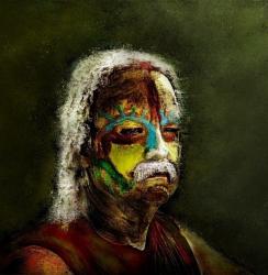
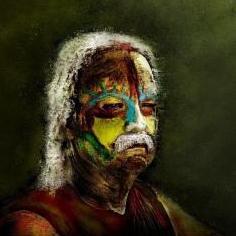
digman's post in reconstruct texture from polypaint was marked as the answer
Yes you can... but might a little different.
This is not a tutorial answer of course...
Attached image...
Model on the left... The orignal scan with vertex colors imported into the sculpt room.
Model on the right... Low polygon model with vertex colors baked and a normal map.
I grabbed this scanned meshed off the net just to show you can... The quality of the vertex paint was low as the model was only about 300,000 polygons.. As you well know the higher the vertex count the higher the quality of your vertex color image.
Also in 3DC there is a way to bake the original high resloution texture image that is from the original scan to the low polygon mesh but this not the subject of this post.
If I have time, I might make a tutorial but I can not promise one for sure.