Add/Split: This tool lets you simply add edges by pointing and clicking on the location you would like to add the edge. Add polygons using the lines between points. In this mode you can add new polygons, as well as split faces and edges, and connect vertices. Use RMB to tweak edges/vertices. See also Add/split addendum. Select: In this mode you can select individual vertices, edges and faces. Use CTRL to remove elements from selection. Select an element with LMB, then move (slide) them with RMB. In ‘Face’ mode use INSERT to subdivide faces and DEL to delete. In ‘Edge’ mode use INSERT to split edges, BKSP to collapse, DEL to remove edges, L to select edge loops, and R to select edge rings, SHIFT to select/highlight edge rings. The select tool has selection modes, allowing you to select Vertices, Edges, and Faces.
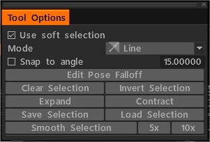
Soft Selection feature in 3DCoat 2023, for the Retopo and Modeling workspaces. It also incorporates the same selection modes from the Pose tool in the Sculpt workspace.
Select Transform: You can initiate Gizmo in the Select Tool by right-clicking the mouse while holding down the Shift key. When you make SHIFT+RIGHT-Click on the vertex, the gizmo isn’t aligned to Normal of this vertex. If you want move along edge, you can Click on the edge.
Make a selection, and right click on ANY OTHER part of the geometry, and the widget aligns to that, allowing to move the selection in a direction matching any existing geometry.
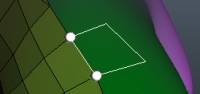
Select Path: Define a seam for Unwrapping by designating a path composed of vertices you select in linear order. Press “Enter” when establishing your path to creating the seam. Quads: The basic usage of this tool allows you to select an edge of a polygon and then drag out and click the placement of the edges for a new polygon. You can use four different methods for defining new topology, one quadrangle at a time. They are 2-click methods, Parallel, Direct and Trapezoid.
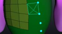
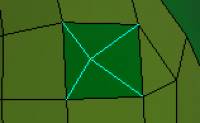
Points to Polygons: Use this tool to create quadrangles or triangles, point by point, hovering the mouse cursor over the area defined by the points and “Right-Clicking” to establish the new polygon. You can move vertices by “Right-Clicking” and dragging them. Add points with LMB. Tweak points and add faces with RMB. (look at preview) Force triangles with SHIFT. Hold cursor close to the center of potential quad for more precise placing of the quad. Use Special Submenu to clear points. Cap: Hovering the mouse cursor over a hole surrounded by connected topology and “Right-Clicking” creates a “pole” and the connecting triangles that close the hole. Strokes Draw strokes and press ENTER to create a poly-surface. Press ESC to clear strokes. Draw with CTRL to add splines and connect and break existing strokes. You can also draw closed splines/curves. Start drawing in space to slice. You can join several slices or circles with a single stroke to create cylinders. Curves/Strokes: Create topological “cuts” that form loops through a model area, or draw freeform splines with an even spacing of vertices that you define in advance. One use for this tool is to define a surrounding cylinder of polygonal rings by first drawing a sequence of loops (start drawing in space and finish in space), then draw a freeform spline along the length of a model “appendage” (arm or leg), and press “Enter” to finalize and create a cylindrical set of faces which define the appendage.
There are a few commands local to this tool under Special SubMenu:
Clear. This will clear all drawing lines.
Smooth. Smooths all current drawn lines.
Delete. This will delete your currently selected line.
Create 3D and 2D primitives
New versions added the boolean operations for retopo primitives in Retopo and Modeling room. You can create primitives using the boolean operations add, subtract, intersect, and split. 3D Primitives: tools for creating 3D primitives for Modeling and Retopo rooms. You can create the 2D primitives (circle, box, plane, ellipse, N-gon, disk, triangle). 2D Primitives: tools for creating 2D primitives for Modeling and Retopo rooms. You can create 3D primitives (spheres, cubes, cylinders, etc.).
Primitives examples
Primitives: Add simple primitives to the scene. You can model a library of meshes, splines, and rotation objects. Use Tool Options Panel to transform the model before applying. Retopo Primitives: This video demonstrates the Primitives Tool in 3DCoat’s Retopo Workspace. It helps to create Retopo mesh objects quickly but can be used as a starting point for poly modeling in 3DCoat, as well. FreeForm Retopo Primitives: This video demonstrates the usage of Retopo Model presets as FreeForm Deformation Primitives within the Retopo workspace of 3DCoat, and a tip on modeling interchangeably between the Retopo and Sculpt environment.
RFill: This video demonstrates the usage of the RFill tool in 3DCoat’s Retopology workspace. It may be renamed “Quad Fill” in the near future, as it fills openings in the mesh with quads. This is a Quad Fill tool designed to fill holes in a mesh with the proper topological flow. Knife: Cut a face with Knife. Draw the line and press ENTER or DblClick. Also, you can draw a polygon by two points. Smart RetopoThe video shows what we call Smart-Retopo feature, based on using the Curves toolset.
Smart Retopo
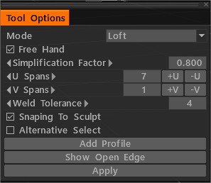
In mode Loftdraw strokes and press ENTER (Apply) to create a loft polysurface (Retopo Mesh). You can draw simple surface-strip in mode Strip. You can draw the boundary of the mesh in mode Quadrangulation.
After pressing Enter, creating preparatory mesh. You can edit the boundary line. Press ENTER (Apply) to create a Retopo Mesh. Press ESC to clear strokes. Hold Shift to turn Snapping off. Start drawing in empty space to slice. Edit Edges by Right Button Mouse. If hold Ctrl activate Slide Edge. If hold Ctrl+Shift activate Splite Rings.
U Spans Specifies the number of nodes in the longest curve. The number of steps in others depends on the length of the curve. If hold Ctrl, you can change U Spans by mouse wheel. Correspondence of Qty USpans/VSpans to Qty of Face. Added check button “Alternative Select”.
Spine Tool: extrude selected faces along Arc. A Transform Gizmo can edit the angle and Axis of the Arc. You can edit the Number of Segments and Scale factor. In Spline Mode, you may LMB drag points to move in 3D space and use the Scroll Wheel on Mouse (or equivalent on Wacom Tablet) to interactively scale the geometry of the edge loop surrounding the point the cursor is over. Each spline point represents a new extrusion. Hitting the ENTER key or the NEW EXTRUDE button in the Tool Options panel creates a new extrusion/point. Double-Clicking along the spline creates an intermediate (edge loop) extrusion/(spline) point, while double-clicking a point removes an (edge loop) extrusion/(spline) point.
Smart Extrude Extrude face or edge in any direction. Hitting the ENTER key creates a new extrusion. You can also interactively scale (RMB + Drag) and rotate (SHIFT + Drag) selected faces or edges.
Free Extrude: Extrude in any direction. Remember that new vertices will not be snapped automatically, but they will snap in further operations if you don’t turn off Auto snap.
Normal Extrude: Extrude along the average normal direction. Remember that new vertices will not be snapped automatically, but they will snap in further operations if you don’t turn off Auto snap.
Extrude Faces: Extrude faces so each face will be moved at the same distance whenever possible. Pay attention that in some cases, exactly parallel faces displacement is impossible, but 3DCoat tries to displace as exactly as possible.
Extrude Vertices: Extrude faces so that each vertex will be displaced on the same distance.
Free Moving: Moving selected faces/edges/vertices. By using a mouse or Gizmo. If nothing is selected entire mesh will be moving. You can move a previously selected group or point with the mouse cursor by pressing the left button. The [Auto pick] option must be activated.
Free Rotating: Rotating selected faces/edges/vertices. By using a mouse or Gizmo. If nothing is selected entire mesh will be Rotating. You can Rotate the previously selected group or point with the mouse cursor by pressing the left button. The [Auto pick] option must be activated.
Free Scaling: Scaling selected faces/edges/vertices. By using a mouse or Gizmo. If nothing is selected entire mesh will be Scaling. You can Scale the previously selected group or point with the mouse cursor by pressing the left button. The [Auto pick] option must be activated.
Make Joints: There are two ways to make elementary bricks for the Joints tool.
Retopo Room Pt.7: Manual Retopo Tools: This video covers some of the Manual Retopology tools in 3D Coat, such as the ADD/SPLIT tool, POINTS & FACES tool, and QUADS tool.
 English
  Українська
 Español
 Deutsch
 Français
 日本語
日本語 Русский
 한국어
한국어 Polski
 中文 (中国)
 Português
 Italiano
 Suomi
Suomi Svenska
 中文 (台灣)
 Dansk
Dansk Slovenčina
 Türkçe
 Nederlands
 Magyar
 ไทย
ไทย हिन्दी
 Ελληνικά
 Tiếng Việt
 Lietuviškai
 Latviešu valoda
 Eesti
Eesti Čeština
 Română
 Norsk Bokmål