Description of all instruments is here

Add Geometry Category
Add/Split: Add polygons using the lines between points. You can add new polygons, split faces, edges, and connect vertices in this mode.
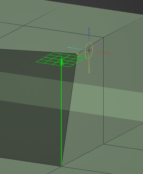
Use RMB to tweak edges/vertices (you can use the Add/Split tool as a target weld tool).
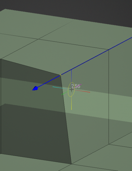
Use the ZX… hotkey combination to move the point(s) in the plane.

Or hotkeys x, y, or z to move along the axes.

Select: In this mode, you can select individual vertices, edges, and faces.

Auto: Choose selection method automatically and clear current selection. Use A shortcut.
Vertices: Operate over vertices. Double-click to select cluster in select mode.
Edges: Operate over edges. Double-click to select cluster in select mode.
Faces: Operate over faces. Double-click to select cluster in select mode.
Object: Operate over object.
Use CTRL to remove elements from the selection.
Select an element with LMB, then move (slide) them with RMB.
- In ‘Face’ mode, use INSERT to subdivide faces and DEL to delete. To select a face loop: hold down Shift and double-click on the second face.
- * In ‘Edge’ mode, use INSERT to split edges, BKSP to collapse, DEL to remove edges, L to select edge loops, R to select edge rings, and SHIFT to select/highlight edge rings.
Initiate Gizmo by right-clicking the mouse while holding down the Shift key.
Select Tool opens a new panel tools at the bottom of Left Tool Panel category (Selected and Entire Mesh); see below this page for this commands.

Select / Transform: Select Vertex/Edges/Faces and Transform by Gizmo. When holding the SHIFT key, you can re-position and orient the Gizmo without applying any transform edits.
Holding the SHIFT + CTRL key will enable hiding of the Gizmo, when needed.
You can locate the gizmo following the normals on the face, edge, and vertex with Shift + RMB.

When you make SHIFT+RIGHT-Click on the vertex, the gizmo isn’t aligned to Normal of this vertex.
If you want move along edge, you can Click on the edge.Make a selection, and right click on ANY OTHER part of the geometry, and the widget aligns to that, allowing to move the selection in a direction matching any existing geometry.
Use Soft Selection: is a feature for the Retopo and Modeling workspaces.
It also incorporates the same smooth selection modes from the Pose tool in the Sculpt workspace.
Select Path: Select the best path in between 2 vertex.
Quads: Select an edge and add a strip of quads.
Points to Polygons: Add points with LMB. Tweak points and add faces with RMB. (look at preview) Force triangles with SHIFT. Hold the cursor close to the center of the potential quad for more precise placement of the quad. Switch to Special command group to Clear Points.
Cap: Cap tool fill holes with a single click.
Hotkey: [C] Use SHIFT to cap holes with a single polygon instead of adding central point. If hold Ctrl, the Center vertex is positioned at the Center Point.
The polygons that are generated when using this tool, will be snapped to the underlaying Sculpt Object.
Strokes/Curves Strokes
STROKES: If you are doing retopologia and have a sculpt mesh as base, draw strokes and press ENTER to create a poly surface.
Press ESC to clear strokes. Draw with CTRL to add splines and connect and break existing strokes.
You can also draw closed splines/curves. Start drawing in space to slice. To create cylinders, you can join several slices or circles with a single stroke.
CURVES/STROKES: It works similarly to the strokes tool but uses curves instead of strokes. It operates only over the curves created within this tool.
Generally, it only considers curves within the ‘CurvesStrokes’ folder in the curves tree.
Primitives
3DCoat offer to create 2 types of primitives. All the primitives have a Tool option where to set the parameters.

3D-Primitives: create 3D Primitives.

2D-Primitives: create 2D Primitives.

R-Fill: This is a Quad Fill tool designed to fill holes in a mesh with the proper topological flow.
Knife: Cut a face by Knife. Draw the line and press ENTER or DblClick.
Also, you can draw a polygon, by two points
Smart Retopo

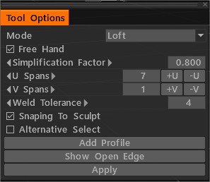
- In mode Loft draw strokes and press ENTER (Apply) to create a loft polysurface (Polygroup).
- You can draw simple surface-strip in mode Strip.
- You can draw the boundary of the mesh in mode Quadrangulation.
- After pressing Enter, creating preparatory mesh. You can edit the boundary line. press ENTER (Apply) to create a Retopo Mesh.
- Press ESC to clear strokes. If you hold Shift the Snaping off. Start drawing in empty space to slice.
- Edit Edges by Right Button Mouse. If hold Ctrl activate Slide Edge.
- U Spans Specifies the number of nodes in the longest curve. The number of steps in others depends on the length of the curve.
- If hold Ctrl, you can change U Spans by mouse wheel. You can Edit the Mesh by Right Button Mouse.
- If press & hold the CTRL key, it will temporarily and on-the-fly, activate the Slide Edge tool.
- If press & hold the CTRL + SHIFT key combination, it will activate the Split Rings tool.
- Correspondence of Qty USpans/VSpans to Qty of Face. Added check button “Alternative Select”.
Smart Retopo The video shows Smart-Retopo feature, based on using the Curves toolset.
There is a variety of Modes

Loft: Hotkey: [L]. This option allows the artist to sketch a path with a Freehand brushstroke and 3DCoat will generate a curve with control points from it.
Strip: Hotkey: [K]. The simplification degree for drawing a free curve. The simplification is applied after you release the pen/mouse.
Quadrangulation: Hotkey: [J]. You must draw the boundary of the mesh. After pressing Enter, creating preparatory mesh.
Points to Polygons: Add points with LMB. Hotkey: [P]
Tweak points and add faces with RMB. (look at preview) Force triangles with SHIFT. Hold cursor close to the center of potential quad for more precise placing of the quad.
Quads: Select an edge and add a strip of quads. Hotkey: [Q].
Add/Split: Add polygons using the lines between points. Hotkey: [A] In this mode you can add new polygons, as well as split faces and edges, and connect vertices. Use RMB to tweak edges/vertices.
Brush: This tool works similar to a soft selection. Hotekey: [B].
Vertices closest to the center of the brush cursor move more than those at the outer edges. Use SHIFT to smooth vertices spacing.
Move: Tweak Vertices, Edges, and Faces.
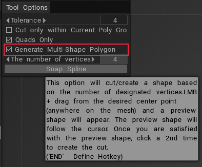
Smart Retopo also have an functionality: Multishape polygon

Smart Extrude: Extrude face or edge in any direction. Hitting the ENTER key creates a new extrusion. You can also interactively scale (RMB + Drag) and rotate (SHIFT + Drag) selected faces or edges.

Extrude modes: use Free Extrude to extrude in any direction. Remember that new vertices will not be snapped automatically, but they will snap in further operations if you don’t turn off Auto snap. Use the other modes to extrude as selection.
Inset: Add polygons to Selected polygons.
Spine Tool: Extrude selected faces along Arc. The angle and axis of the Arc can be edited by a Transform Gizmo. You can edit the Quantity of Segments and Scale factor.
In Spline Mode, you may LMB drag points to move in 3D space and use the Scroll Wheel on Mouse (or equivalent on Wacom Tablet) to interactively scale the geometry of the edge loop surrounding the point the cursor is over.
Each spline point represents a new extrusion. Hitting the ENTER key or the NEW EXTRUDE button, in the Tool Options panel, creates a new extrusion/point.
Double-Clicking along the spline creates an intermediate (edgeloop) extrusion/(spline) point, while double-clicking a point removes an (edgeloop) extrusion/(spline) point.
Free move / Rotate / Scale

Free Moving: Moving selected faces/edges/vertices. By using a mouse or Gizmo.
If nothing is selected entire mesh will be moving. You can move a previously selected group or point with the mouse cursor by pressing the left button. The [Auto pick] option must be activated.
Free Rotating: Rotating selected faces/edges/vertices. By using mouse or Gizmo.
If nothing is selected entire mesh will be Rotating. You can Rotating the previously selected group or by pointing with the mouse cursor by pressing the left button. The [Auto pick] option must be activated.
Free Scaling: Scaling selected faces/edges/vertices. By using mouse or Gizmo.
If nothing is selected entire mesh will be Scaling. You can Scaling the previously selected group or by pointing with the mouse cursor by pressing the left button. The [Auto pick] option must be activated.
Make Joints: There are ways to make elementary bricks for Joints tool.
Surface Swept

Surface Swept: Mesh generating by moving profile along selected curve-guide. The grid step frequency is regulated in 2 directions by U,V Spanse. It is also possible to insert additional edge rings at the desired location with a double click near the thick pink or blue curve.
Added mode: “Twist Plots Editable”. The ability to control the rotation along the track sections.
If mode “Twist Plots Editable” is enable, you can divide the Plot by DblCklick Mouse.
In Surface Swept Tool mode, Scaling is available along the X / Y axes.
Surface Strip: A stripe can be created by drawing a centerline. The width of the strip you can edit near spline points with the mouse wheel. You can insert and delete spline points by DblClick. Press Esc to Start drawing other Curves.
Profile: Mesh generating by moving profile along Axis or selected curve-guide. The grid step frequency is regulated in 2 directions by U and V Spanse.
Surface Swept 2: Mesh generating by moving profile along two selected curve-guide. The grid step frequency is regulated in 2 directions by U and V Spanse.
Swept Surface N Geners: The Sweep Surfaces will be generated by moving N profiles along two curve-guide. After appearing Tool Options dialog, You need to select the second guide and curve profiles. The new item in VoxTree will be created, and the mesh will be placed there.
Select the corresponding object in SculptTree to be able to change parameters like thickness, Quantity of facets, and smoothing. Delete the corresponding SculptTree element to stop filling the curve.
Revolve and Polyhedron
Surface Revolve: The Rotate surface will be generated by revolution of the selected profile around the selected curve axis. The grid step frequency is regulated in 2 directions by U and V Spanse.
Polyhedron: The Polyhedron will be generated by revolution and moving the selected profile around the selected curve-axis. The grid step frequency is regulated in 2 directions by U,V Spanse.
Surface 2 views
Surface by 2 Views: The Mesh generated by moving two conics along the curve guide. You can edit the curve. “Surface by 2 Views” is not enabled in the Z-Up coordinate system.
Surface by two view: The Mesh generating by moving Conic along curves-guide. You can edit curves and two Parameters of Conic.
Loft Surface: Loft Surfaces are surfaces generated by multiple Curves creating a smooth tangency between the selected curves. Mesh generating by moving across selected curve-section. The grid step frequency is regulated in 2 directions by U and V Spanse.
Loft surface example by Fluffy: Loft Surfaces are surfaces generated by multiple Curves-sections creating a smooth tangency between the selected curves.
All curves can be preselected. Mesh generating by moving across selected curve-section.
Additionally you can set guides (Cross-sections).
The grid step frequency is regulated in 2 directions by U,V Spanse. It is also possible to insert additional edge rings at the desired location with a double click near the thick pink or blue curve
Surface Patch: Selected curves define the Boundary and geometry of the Mesh. The grid step frequency is regulated by U Spanse.
Array of copies: You can create copies for selected faces or the current Poly Groups. You need to specify the number of copies for linear and radial types. For copies along a spline, specify the number of steps.

Lattice (Wireframe to Mesh): Lattice will be generated from edges or selected faces.
The width can be changed using the sensitive circle. Moving the cursor horizontally changes the width and vertical depth.
On version 2023.25 an above the “Mesh to NURBS” tool from the Modeling room was removed.
Tool “Mesh to NURBS” is now only in the NURBS room.
Tutorials
New possibilities with installation the gizmo with Shift + RMB: Now you can install the gizmo on the face, edge, and vertex with Shift + RMB.
Smart Extrude part 2
Smart Extrude in 3DCoat Part2: Extrude tools have been modified as requested by users. With a new selection, the extrude is automatic when the movement starts. The possibility of working as before is left for Smart Extrude.
Smart Extrude part 3
 Ελληνικά
  English
 Українська
 Español
 Deutsch
 Français
 日本語
日本語 Русский
 한국어
한국어 Polski
 中文 (中国)
 Português
 Italiano
 Suomi
Suomi Svenska
 中文 (台灣)
 Dansk
Dansk Slovenčina
 Türkçe
 Nederlands
 Magyar
 ไทย
ไทย हिन्दी
 Tiếng Việt
 Lietuviškai
 Latviešu valoda
 Eesti
Eesti Čeština
 Română
 Norsk Bokmål