The “Microvertex” mode
This mode allows you to export either standard displacement maps that accurately reflect the more extreme levels of displacement you have added by means of textures or sculpting.
In this approach, every face was represented as a patch (face) of N (size) x M (shape) vertices (N and M could be different for every face).
As every vertex had color and coordinates in space, so any displacement was allowed.
3DCoat add tris on every nGon faces to avoid painting issues.
This approach was limited because it was very difficult to edit mesh with non-quad faces because quad faces only allowed. So working with nGons projecting patch to texture resulted in the loss of quality, so it was difficult to import a texture, edit it and then export because the after-export texture appeared to be slightly blurred.
If you only need to export normal maps to simulate lighting, use the per-pixel painting mode.
Import for MV
The mesh consists of two levels of detail: display mesh (mid – poly mesh) and high resolution mesh.
Millions of polygons: Mesh resolution, in millions of polygons, after the mesh smoothing is applied during the loading. This amount should be greater than the number of pixels in the texture.
This mesh resolution is what is going to drive the displacement map painting.
We need a one-by-one correspondence between the vertices on a model and the pixels on a UV map so if you have a 2k map 3DCoat recommends that you essentially multiply the size of your map basically x2, and you come up with 4 million polygons.
As example if you have 3 UV-set with 2k maps each one, you have a 6k map so we multiply 6k by 4k and that wild leave with 36 millions polygons.
Display Mesh Resolution:
Usually you see the mid-poly mesh in the viewport with a normal map created using the high-poly mesh. MV (displacement) painting actually modifies a temporary “viewport mesh”, which is a user-defined subdivided version of your base mesh applying real and actual displacement to this temporary mesh.
Improve visualization on View > Adjust Tessellation: You can improve visual appearance of mesh displacement using additional tessellation of faces.
Faces are represented as a grid NxN over every face. Use this options only if you are sure that your video card can support the additional processing.
Import Tiles as UV Sets: Import separate UV tiles as separate UV sets (uDims).
Smooth with Catmull-Clark: Specify if CC smoothing is required. Otherwise, the flat subdivision is applied.
Just one little explanation:
Another Reason to use Microvertex Mode is that it supports Flat Subdivision, it even respects Hard Edges. And the Preview Display of the Mid Poly Mesh is just excellent!
PPP on the other Hand turns everything into a ball (Catmull-Clark) as soon as you turn on Subdivision.
Invert Normals: Invert faces normals. Use this function if object looks like flipped.
Weld Vertices: Weld separate vertices that are at the same point in space.
Z-up Coordinate System: Z-up based coordinate system for compatibility with Rhino, 3DS-Max, and other applications with Z-axis up.
No Center Snap: 3DCoat tries to move bound box of the model to the origin of the scene by default. Check this box if you want to import model as is, without any centering.
Mapping type
To load the model in microvertex representation 3DCoat requires one to one correspondence between the texture and surface points; one point on the UV-Map should correspond to only one point on the surface.
If your object meets this requirement, select Keep UV: Specify what kind of texture coordinates should be used during the edit process.
Even if your model has symmetry or overlaps (but not self-overlaps) you can load it with the Keep clusters: Choose this option if your model has overlaps in UV-mapping.
3DCoat will put all clusters (UV islands) over one texture without overlaps.
This will move clusters (Uv islands) so they do not overlap.
Auto-Mapping: This option provides automatic UV-mapping. While the result is usually satisfactory, unmapped or complex convex shapes should be mapped manually.
Try to avoid self overlapping clusters, and complex, non-convex polygonal shapes. Ideally, objects with no UV-mapping should be manually mapped, but selecting Auto-mapping will yield good results.
UV Sub-Patch Smoothing: The type of smoothing that will be applied to UV islands.
- No Smoothing: UV-sub patches will not be smoothed.
- Smooth, Keep Edges: UV-set will be smoothed but edges of islands will keep positions.
- Full UV Set Smoothing: The UV set will be completely smoothed.
- Smooth But Keep Corners: Smooth the UV-set and even out the boundaries, but keep the corners unsmoothed.
If you are editing architectural or non-organic shapes disable smoothing for best results. In this case you will be able to export the current displacement and normal maps.
Preserve Positions: Compensate for shifting vertices caused by the smoothing required for additional extrusion.
Ignore Smoothing Groups: Ignore the original smoothing groups in the object.
Auto Smoothing Groups: Automatically create smoothing groups when this option is enabled.
UVset name and Texture size:
Painting displacement
When you need to provide your model with high levels of “actual” displacement by means of sculpting and “painting” this displacement, the best mode to use is the “Microvertex” mode.
Displacement mapping is an alternative computer graphics technique in contrast to bump mapping, normal mapping, and parallax mapping.
Displacement Map allows you to shift the grid points on the surface of the painted object. This technique is used to create a color depth or relief on a hard surface. This allows you to draw textures in more detail and create shadows and clear silhouettes.
Use a texture or height map to cause an effect where the actual geometric position of points over the textured surface are displaced, often along the local surface normal, according to the value the texture function evaluates to at each point on the surface.
It gives surfaces a great sense of depth and detail, permitting self-occlusion, self-shadowing, and silhouettes; on the other hand, it is the most costly of this class of techniques owing to a large amount of additional geometry.
A normal map generated by Per Pixel Painting is used to simulate lighting. MV allows you to create roughness and depth of folds or depressions. The function also allows you to add a lot of small details to the 3D model.
Displacement only works when there is enough geometry (faces) on the object surface to move the individual vertices up or down based on the pixel’s color in the height map.
If the designer uses a low-poly model, the Displacement Map and the effects that it creates are practically invisible. Therefore, such a thorough drawing does not make sense in this case. The full potential is revealed when working with a high-poly model.
Importing displacement textures
Micro-vertex painting is true displacement painting in real time and made for that. You export your low polygon mesh at then end and apply that displacement map in the game or renderer of your choice. You can also export a normal map.
As you can see, there is no Show displaced mesh in micro-vertex mode. There is no need of it, your depth painting is already displacing as you paint your depth.
You still can tessellate (View > Adjust Tessellation) more still but generally it is not necessary.
If you go into per pixel mode and turn on show displaced mesh, turn on wireframe mode and do some depth painting, you will notice that the wireframe mesh is not really displaced.
If you go into micro-vertex mode and do the same, you will see the true polygons being displaced on the display mesh subdivision level you chose when you imported or baked to the paint room.
Remember though that the displacement map that is being created in the paint room is done in real time and applied to the mesh as you paint. The millions of polygons use to create the displacement map on the fly is an internal operation as explained in the video.
This also helps on exporting as you can export the low polygon mesh with how the model was displaced in the paint so that it better fits the model when it is subdivided in your game engine or renderer. That is an option you can choose.
Exporting textures
When the texture is exported (File > Export) it will be saved using the original UV-coordinates. If a mapping conflict is detected, the more painted pixels will be preferred. So feel free to load objects with symmetry and overlaps.
This settings are self explanatory, and you can also read the hints that popups when you hold LMB over any command.
Upon export of your model and its associated textures, you are given the option of setting the finished mesh density.
- High poly Mesh: 3 options to export a high-polygon mesh.
The high-poly mesh has four times more polygons than a medium-poly mesh.
The high-poly mesh has sixteen times more polygons than a medium-poly mesh.
The high-poly mesh has sixty-four times more polygons than a mid-poly mesh.
To ensure that your model can accurately represent the displacement achieved in real-time in the viewport, make sure you give it adequate polygon density (10’s or hundreds of thousands of polygons).
Watch this video on Micro-vertex painting. It a 3 years old video but still valid at least on the information about microvertex painting.
The video bakes from the retopo room but you can import for micro-vertex painting from the File menu.
NxM vertices representation
What “N x M vertices (N and M could be different for every face)” means in 3D modeling:
Patch Representation with Variable N x M Vertices:
This describes a method for representing individual faces (quads only) in a 3D model.
Here’s the breakdown:
- Patch: A patch refers to a small, defined section of a larger mesh. In this case, each face of the model is considered a separate patch.
- N x M Vertices: This defines the size and shape of the patch using the number of vertices (points) along its width (N) and height (M).
- Variable N and M: Unlike a traditional quad (four vertices), N and M can be different for each face. This allows for more flexibility in representing faces with irregular shapes.
For example:
- A flat, square face might be represented by a 4 x 4 patch (N = 4, M = 4), which is essentially a standard quad.
- A triangular face could be represented by a 3 x 3 patch (N = 3, M = 3) or a 4 x 2 patch (N = 4, M = 2) depending on the specific shape.
- A curved face might be represented by a patch with more vertices on one side compared to the other (e.g., N = 6, M = 4).
This approach offers advantages like:
- Adaptability: It can represent faces of various shapes and sizes without resorting to complex polygon structures.
- Efficiency: Patches with fewer vertices for simpler faces can potentially reduce the overall polygon count of the model, improving performance.
However, there are also potential drawbacks:
- Complexity: Managing and manipulating patches with variable vertex counts can be more complex compared to using uniform quads.
- Compatibility: Not all 3D modeling software might natively support this representation.
Overall, representing faces with variable N x M vertices is a technique used in certain 3D modeling scenarios where flexibility in patch shape is desired.
Examples of NxM vertices modeling
Here are some examples of 3D modeling scenarios where representing faces with variable N x M vertices is useful:
- Facial Animation: When animating faces, especially for characters with a wide range of expressions, using a fixed number of vertices can lead to unnatural deformations. By allowing faces to have a variable number of vertices, animators can achieve more nuanced and detailed expressions. For example, areas around the mouth and eyes might have a higher N x M value to capture subtle wrinkles and folds.
- Character Creation: Creating detailed characters with unique features often benefits from having variable-sized faces. This allows for intricate details like wrinkles, scars, or specific facial structures to be modeled more accurately. By adjusting the N x M values in different regions, artists can achieve a more realistic and customized look.
- Procedural Modeling: Techniques like procedural generation of terrain or natural objects can leverage variable N x M faces. Imagine mountains with jagged peaks – these areas might require more vertices (higher N x M) compared to flatter valleys. This allows for efficient creation of complex shapes with varying levels of detail.
- Level of Detail (LOD): In video games or large-scale environments, rendering efficiency is crucial. Using variable N x M faces allows for creating different levels of detail for a single object. When an object is far away, a lower N x M value can be used for a less detailed representation, saving on processing power. As the object gets closer, the N x M value can be increased to show more detail.
Tutorials
Painting With Multiple Real Displacement Textures (The Quick Explanation): This is a quick tutorial on how to paint with Tessellated displacement using Christoph Schindelar’s awesome 4-8K “Real Displacement Textures” in 3DCoat. Additionally, you can use IBL (image-based lighting) to have your model lit by the background image to have the appearance that it belongs in the photo but also help you to envision your creation.
Import to Microvertex Options Notes: This video mentions some quick and important notes about importing a model into the Painting Room using the MicroVertex (displacement map in-depth channel) option.
What is Displacement maps ? by Chipp Walters, Displacement only works when there is enough geometry (faces) on the object surface to move the individual vertices up or down based on the pixel’s color in the height map.
Displacement is where you use a grayscale image to generate significant topology.
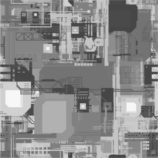
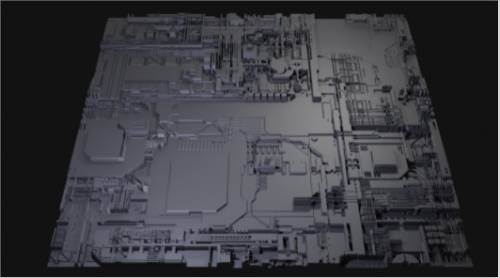
Here is an example of a grayscale “map.” Note I used the wonderful (and free) app JSplacement to create this one.
You can see when a displacement map is applied correctly, the light areas in the grayscale image are “higher” than darker areas.