• Norsk Bokmål
  • 3DCoat dokumentasjon
  • Chapters
    • Introduksjon til 3DCoat
    • Starter
    • Grensesnitt og navigasjon
    • Brush
    • Node System
    • GPU Texturing
    • Arbeidsrom Rom
    • Scripting og Core API
    • Spørsmål og svar
    • Licensing
  • Learn
    • Getting Started
    • Painting
    • Sculpt
    • Modeling
    • Retopology
    • UV
    • Smart Materials
    • Nodes
    • Photogrammetry
    • Render
    • Print
    • Learning
    • Opplæringsveiledninger
  • Blog
    • Texturing with nodes
    • Shader Nodes VS. a Material Nodes
    • Multiple UV Tiles/UDIMs to one single UV set ?
    • I want to create geometry only with displacement to be manufactured with a CNC machine
    • Creating 3D Character Using 3DCoat
    • DAZ Genesis models into 3DCoat
    • Cavity and Curvature maps
    • Types of normal maps
    • Texture painting pipeline
    • Load new UV layout After Model Changes
    • Import Zbrush Polygroups for UV mapping
  • Products
    • 3DCoat
    • 3DCoatTextura
    • 3DCoatPrint
    • PBRLibrary
  • Store
  • Pilgway
  • Norsk Bokmål Norsk Bokmål
    • English English
    • Українська Українська
    • Español Español
    • Deutsch Deutsch
    • Français Français
    • 日本語 日本語
    • Русский Русский
    • 한국어 한국어
    • Polski Polski
    • 中文 (中国) 中文 (中国)
    • Português Português
    • Italiano Italiano
    • Suomi Suomi
    • Svenska Svenska
    • 中文 (台灣) 中文 (台灣)
    • Dansk Dansk
    • Slovenčina Slovenčina
    • Türkçe Türkçe
    • Nederlands Nederlands
    • Magyar Magyar
    • ไทย ไทย
    • हिन्दी हिन्दी
    • Ελληνικά Ελληνικά
    • Tiếng Việt Tiếng Việt
    • Lietuviškai Lietuviškai
    • Latviešu valoda Latviešu valoda
    • Eesti Eesti
    • Čeština Čeština
    • Română Română
  • 3DCoat dokumentasjon
  • Chapters
    • Introduksjon til 3DCoat
    • Starter
    • Grensesnitt og navigasjon
    • Brush
    • Node System
    • GPU Texturing
    • Arbeidsrom Rom
    • Scripting og Core API
    • Spørsmål og svar
    • Licensing
  • Learn
    • Getting Started
    • Painting
    • Sculpt
    • Modeling
    • Retopology
    • UV
    • Smart Materials
    • Nodes
    • Photogrammetry
    • Render
    • Print
    • Learning
    • Opplæringsveiledninger
  • Blog
    • Texturing with nodes
    • Shader Nodes VS. a Material Nodes
    • Multiple UV Tiles/UDIMs to one single UV set ?
    • I want to create geometry only with displacement to be manufactured with a CNC machine
    • Creating 3D Character Using 3DCoat
    • DAZ Genesis models into 3DCoat
    • Cavity and Curvature maps
    • Types of normal maps
    • Texture painting pipeline
    • Load new UV layout After Model Changes
    • Import Zbrush Polygroups for UV mapping
  • Products
    • 3DCoat
    • 3DCoatTextura
    • 3DCoatPrint
    • PBRLibrary
  • Store
  • Pilgway
  • Norsk Bokmål Norsk Bokmål
    • English English
    • Українська Українська
    • Español Español
    • Deutsch Deutsch
    • Français Français
    • 日本語 日本語
    • Русский Русский
    • 한국어 한국어
    • Polski Polski
    • 中文 (中国) 中文 (中国)
    • Português Português
    • Italiano Italiano
    • Suomi Suomi
    • Svenska Svenska
    • 中文 (台灣) 中文 (台灣)
    • Dansk Dansk
    • Slovenčina Slovenčina
    • Türkçe Türkçe
    • Nederlands Nederlands
    • Magyar Magyar
    • ไทย ไทย
    • हिन्दी हिन्दी
    • Ελληνικά Ελληνικά
    • Tiếng Việt Tiếng Việt
    • Lietuviškai Lietuviškai
    • Latviešu valoda Latviešu valoda
    • Eesti Eesti
    • Čeština Čeština
    • Română Română
Expand All Collapse All
  • Introduksjon til 3DCoat
  • Starter
    • System requirements
    • Why 3DCoat is Unique?
    • Aktiverer 3DCoat
    • Oppstartsfeil
      • Startup error Mac
    • Color management
    • Upgrading permanent license
    • Linux Setup
      • Linux initial setup per-user installation
      • Linux initial setup for system
      • Tablet setup
      • To GTK3 from GTK2
      • Error libicuuc.so.70
    • Mappestruktur
      • Custom documents folder
    • Ulike former for "oppløsning"
    • Tablet on Window
    • Import og Export
    • Applinks i 3DCoat
      • Blender applink
        • Blender with the Applink in Linux
      • Blender 4.2/3/4/5 applink
      • Max Applink
      • Houdini applink
      • Lightwave uplink
  • Navigation
    • Åpningsdialog (hurtigstartmeny)
    • Navigasjonspanel
    • Kamera og navigasjon
      • Customize Navigation as Blender
    • Viewport Navigation Gizmo
    • Left tool panel
    •  Activity Bar
    • Navigering ved hjelp av 3DConnexion-enheter
      • How to compile Spacenavd on non Ubuntu distro
    • Quick Access Menu
    • Stylus doesn’t work in sculpting
    • Hurtigtaster
  • Grensesnitt og navigasjon
    • Filmeny
    • Rediger meny
      • Calculate Curvature
      • Calculate Occlusion
      • Light Baking Tool
      • Preferanser
    • Vis meny
    • Symmetri
    • Textures
    • Calculate
    • Lagmeny
    • Frys meny
    • Hide
    • Bake
    • Kurver 2022
      • Kurvermeny
      • Curves Properties RMB
      • Fyll med mesh-lag
      • Scale of imported curves
    • Windows-menyen
      • Windows Popup-paneler med faner
      • Skyveknapper
    • Scripts
    • Addons
    • Capture
    • Hjelp-menyen
    • Tilpasning
    • Endre eller opprett nytt rom
  • Brush
    • Brush Top Bar
    • Børster til generell bruk
      • Lag børster og dekaler
      • Å lage alfa fra nåværende skulptur
      • Lag en Brush fra et 3D-objekt
      • Create brushes based on Curves
      • Load photoshop .abr brushes
    • Slag
      • Kurver popup-meny
    • Brush
    • Betingelsesbegrenser
    • Strips Panel
    • Sjablonger panel
    • Smarte materialer
      • Legg til nye bilder eller materialer
      • Fest et Smart-materiale til et lag
      • Import Quixel Megascans
    • Hvordan lage forhåndsinnstillinger for Brush
  • Node System
    • Node Editor
    • Node & Object Inspectors
    • Node Graph
    • NodeGraph Language (NGL)
    • GPU Nodes
      • Color
      • GeometryIn
      • In
      • Layer
      • Material
      • Out
      • Pattern
      • Pattern3D
      • ShaderToy
      • Shape
      • Texture
      • Tilable
      • UV
      • Math
    • Filters
    • Masks
    • Materials
    • Modifiers
    • Volumes
  • Gratis 3DCoatPrint
  • GPU Texturing
    • PBM Channels
    • Per-Pixel Painting
  • Arbeidsrom Rom
    • Painting
      • Painting og modi
        • Per-Pixel Painting
        • Painting (Micro-Vertex)
        • Ptex Painting
        • Painting (polymaling)
      • Importerer inn i Painting
        • Initial CC subdivision
        • UV Set smoothing
        • Sharp (hard) edge
        • Lås Normaler
        • Last inn ny UV layout etter modellendringer
        • DAZ Genesis models into 3DCoat
        • ID map
      • Menyer for Painting
        • Edit menu
        • Teksturmeny
          • Baking
        • Gjemme seg
        • Meny for Bake Paint
        • Fargevelgeren
      • Surface Materials
      • Toppstang for Painting
      • Lagpanelet
        • Blandingspanelet
        • Layer and Clipping Masks
      • Painting
      • Opasitet - Gjennomsiktighet
      • Juster arbeidsområdet
        • Tweak verktøysett
        • Eksporterer fra Tweak Room
      • Forhåndsvisningspanel for maske/materiale
      • Eksporterer fra Painting
    • UV arbeidsplass
      • UV toppbar
      • UV Venstre verktøypanel
      • UV forhåndsvisningspanel
      • Eksempel på UV arbeidsflyt
      • Importerer inn i UV rommet
      • Eksporterer fra UV rommet
    • Retopologi
      • Importerer til Retopo rommet
      • Retopo Mesh Menu og Bake Menu
        • Virtuelt speilmodus
      • Bake menu
        • Treat Poly Groups as Paint Objects
        • Baking guide
      • Strokes-verktøy i Retopologi
      • Toppbar
        • Velg geometri
      • Venstre verktøypanel i Retopologirom
        • Overordnet formål og funksjon
        • Legg til geometri
        • Retopo Tweak-verktøy
        • UV verktøy
        • Kommandoer for Retopologirom
      • AUTORETOPO
        • Autopo guide
      • Polygrupper
    • Skulptere
      • Sculpt Layer
      • Skulptre
      • Sculpt Brush alternativer
      • Top Bar
      • Brush
      • Geometri Undermeny
      • Skulptér "høyreklikk"-menyen
      • Shaders
      • Voxel modus
        • Ren Voxel skulptur
        • Tetthet og oppløsning
        • Leiremotor
        • Voxel verktøy
        • Overflateverktøy på Voxels
        • Voxel justeringsverktøy
        • Volumetrisk Painting
        • Voxel Objects-verktøy
      • Overflatemodus
        • Overflateverktøy
        • Tilpassede overflateverktøy
        • Surface Layer
        • Overflatejusteringsverktøy
        • Painting
        • Flernivåoppløsning
          • Multires tools
          • Multires adjust
          • Multires commands
      • Skulptere kurver
        • Splinekurver
        • Splines model creation
      • Vektor forskyvning
      • Verktøy for overflatetransformasjon
        • Voxel Transform Tools
        • Instancer
        • Move
        • Pose
        • Fit
        • Reproject
        • Surface Array
      • Voxel Primitives og Import
        • Hollow Box
      • Levende booleanere
      • Kommandoer for Sculpt-rommet
      • Import til Sculpt Room
      • Eksporterer fra Sculpt Room
    • Gjengi
      • Comparison of different roughness values
      • Gjengi panelfunksjoner
      • Platespiller
      • Fakebake the lighting -ikke PBR-
    • Factures
      • Arbeidsflyt
    • Enkleste
    • Modellering
      • Mesh Menu
      • Venstre verktøypanel i modelleringsrommet
        • Legg til geometri
          • Make Joints
          • Valgt
        • Tweak
        • Smart Hybrid
        • UV
          • Kommandoer
        • Hele mesh
      • Loft overflate eksempel av Fluffy
      • Blockout av Poeboi
      • Import Zbrush Polygroups for UV mapping
    • Kitbash - Rask oppretting av 3D-modeller
      • Create kitbash
      • Left tool panel Kitbash
    • 3DPrint
    • Photogrammetry
      • How to install Reality Capture
      • Reality Capture doesn’t show up ?
    • Mesh til NURBS-rommet
    • Nodes
      • Texturing with nodes
      • Sculpt shaders Nodes Library
      • Open PBR
  • Scripting og Core API
    • Core API
    • Python API
    • Extensions and Addons

Make Joints

60 views 0

Written by Carlos
July 26, 2026
image.png

There are 2 ways to make elementary bricks for Joints tool.

  1. Make joints in 3DCoat. Read this document.
  2. Make joints in some external editor. Read the specifications. 

Technical requirements for models with Joints

  • The model should be created taking into account the scale of the grid. For example, if it is a cube, then 10*10*10, a brick – 20*10*10.
    The blocks could be larger, however, they should be made to apply neatly onto the grid of 10*10*10.
    The vertical axis is Y.
    If the model is a tube, then the diameter should be 5.
    If the tube’s corner, then any parameter taking into account the corner is applied to the tube of 5 in the diameter. 
  • You may add joints to the model right in 3DCoat. For this purpose, please make the model in the Modeling room (sculpt and retopo or model in the Modeling room from scratch).

Then go to Modeling room->Make joints and add as many joints as you need. It looks like:
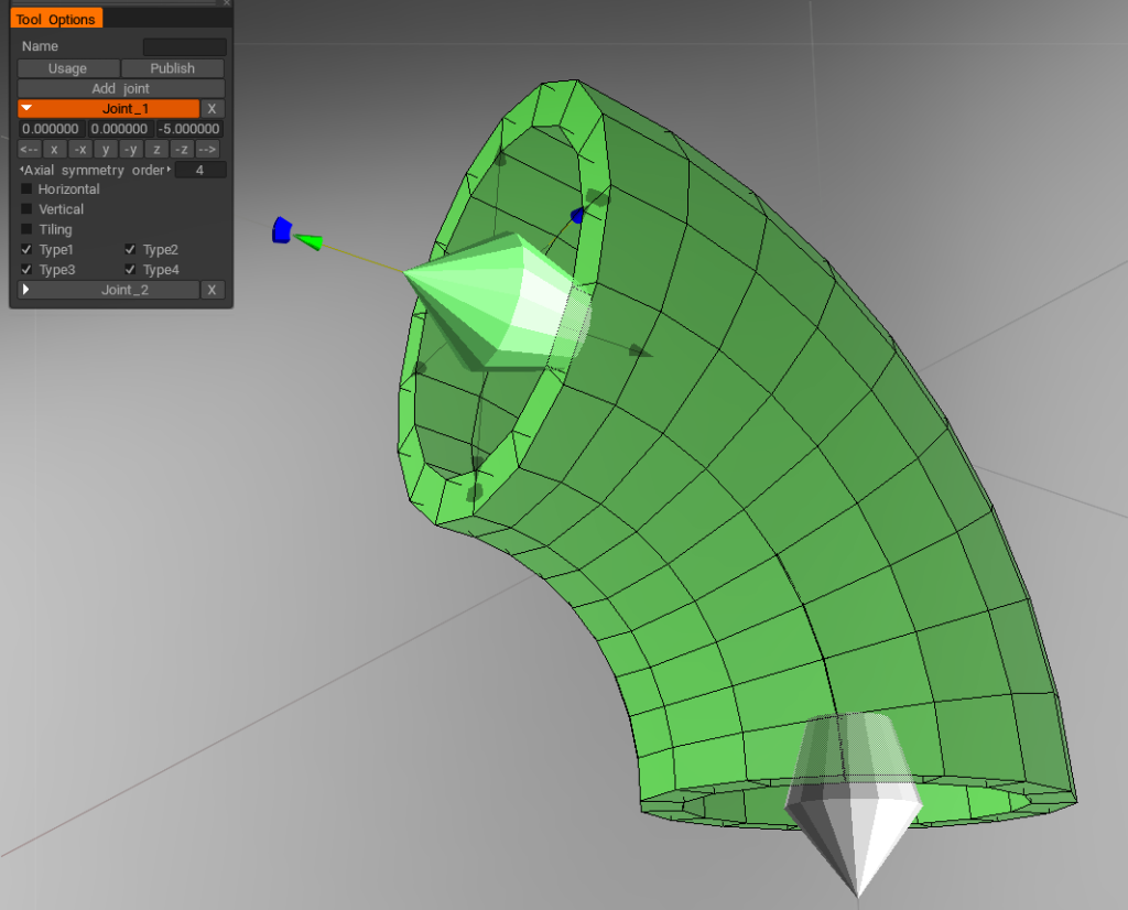
  • Press Add joint to add new joint. There are several options for each joint – axial symmetry, vertical/horizontal alignment, compatibility with other joints.
  • Please fill in the name of the model and press Publish as soon as the model with joints is ready. The model will be placed in the Joints palette and you will get to the Joints tool to test the model with joints. Pay attention that the model with the same name.
  • Model requirements. The models are low-poly ones – up to 5К polygons per model.
  • If there is a tube 16 segments should be created. 
  • A model could be a composite one. If there is a sub-object (retopo group) with the name of Shader_Gold, there will be created a volume named Shader_Gold, where the subobjects of this type will be gathered.
  • That volume will be assigned a shader whose which name fits best with the word of Gold.
  • Examples of models with the joints put Here
  • The ready-made models should be placed Here

JOINTS SPECIFICATIONS

Technical requirements for models with Joints

  1. The model should be created taking into account the scale of the grid. For example, if it is a cube, then 10*10*10, a brick – 20*10*10. The blocks could be larger, however they should be made to apply neatly onto the grid of 10*10*10. The vertical axis is Y. If the model is a tube, then the diameter should be 5. If the tube’s corner, then any parameter taking into account the corner is applied to the tube of 5 in the diameter. 
  2. The model should consist of the very model to insert into the scene and the Joints. The Joints are objects in the scene which names start from the word Joint …. 

Each Joint is a pyramid or a cone, the sharp angle is directed outwards from the object. The center of the parallelepiped around the Joint is the point where the Joints connect.
Here’s an example of an object with the Joints. A curved tube – the object, cones – the Joints.
The very Joints are not added to the scene, but only the object.   
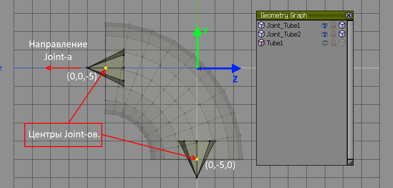
Joints without the object.

Placement of the Joints on the mesh. The division value is 1.

  1. Agreements on the names of the Joints. The name of the Joint is the name of an object where the joint is located. The name may consist of several tags, for example Joint_Vertical_Axial16_Type1_Type2_01
    – The Joint object always starts with the word Joint_
    – The object name may contain key lines which define the behavior model for 3DCoat. Below is a set of sublines allowed:
    – Horizontal – the Joint is always horizontal
    – Vertical –  the Joint is always vertical
    – Tile – the Joint is tiled; user can pull the object alongside the direction of the Joint and multiply the object. This flag is rarely specified manually. The Joint is considered tiled if it is directed along one of the axes and there is a Joint in the opposite direction and with an opposite coordinate.

– AxialХХ, where XX is multiple of the axis symmetry. For example Axial4 can be rotated at 90 degrees, Axial8 can be rotated at 45 degrees.
– Type1, Type2, Type3, Type4 – the joints can be of various types. If there no particular type specified, the joint is compatible with all the types. You can specify several types using the _ sign. Then the Joint will be compatible with the specified types only. 

  1. Model requirements. The models are low-poly ones – up to 5К polygons per model. If there is a tube designed – 16 segments should created. 
  2. 3DCoat automatically creates a facet on all the edges with the angle of sharper than 140 degrees. However, if the name of the object contains the word “Soft” or “Native”, or two underlines is a row “__”, the facet is not created.
  3. A model could be a composite one. If there is an object with the name of Shader_Gold, there will be created a volume named Shader_Gold, where the subobjects of this type will be gathered. That volume will be assigned a shader which name fits best with the word of Gold.
  4. Adding models to 3DCoat. Show the window with models – Windows->Popups->Joints. In that window we add the model. The models should be distributed by the categories, don’t throw everything into one pile.
  5. Examples of models with the joints put Here
  6. The ready-made models should be placed Here

Tutorials

Joints in 3DCoat: In this video, I will explain the use of Joints in 3DCoat.

Tags:make jointsmodeling

Was this helpful?

Yes  No
Related Articles
  • Texturing with nodes
  • Hollow Box
  • GPU Texturing
  • Math
  • Volumes
  • Modifiers
Previously
Legg til geometri
Up Next
Valgt
AI:
Hi! How can I help you?
Attention: This is a beta version of AI chat. Some answers may be wrong. See full version of AI chat