한국어
한국어  English
 Українська
 Español
 Deutsch
 Français
 日本語
日本語 Русский
 Polski
 中文 (中国)
 Português
 Italiano
 Suomi
Suomi Svenska
 中文 (台灣)
 Dansk
Dansk Slovenčina
 Türkçe
 Nederlands
 Magyar
 ไทย
ไทย हिन्दी
 Ελληνικά
 Tiếng Việt
 Lietuviškai
 Latviešu valoda
 Eesti
Eesti Čeština
 Română
 Norsk Bokmål
이 변위를 조각하거나 “페인팅”하여 높은 수준의 “실제” 변위를 모델에 제공해야 하는 경우 사용하기에 가장 좋은 모드는 “Microvertex” 모드입니다.
변위 mapping 텍스처 또는 높이 맵을 사용하여 텍스처 표면 위 점의 실제 기하학적 위치가 종종 로컬 표면을 따라 변위되는 효과를 일으키는 범프 mapping, 일반 mapping 및 시차 mapping 과 대조되는 대체 컴퓨터 그래픽 기술입니다. 텍스처 함수가 표면의 각 지점에서 평가하는 값에 따라 정상입니다.
표면에 뛰어난 깊이감과 디테일을 제공하여 자체 폐색, 자체 그림자 및 실루엣을 허용합니다. 다른 한편으로는 많은 추가 지오메트리로 인해 이러한 종류의 기술 중 가장 비용이 많이 듭니다.
변위 맵을 사용하면 페인팅된 개체 표면의 격자점을 이동할 수 있습니다. 이 기술은 딱딱한 표면에 색상 깊이 또는 양각을 만드는 데 사용됩니다. 이를 통해 텍스처를 더 자세히 그릴 수 있고 그림자와 선명한 실루엣을 만들 수 있습니다.
normal map 조명을 시뮬레이트하는 데 사용됩니다. 이 도구를 사용하면 주름 또는 함몰의 거칠기와 깊이를 만들 수 있습니다. 이 기능을 사용하면 3D 모델에 작은 세부 정보를 많이 추가할 수도 있습니다.
변위는 개체 표면에 높이 맵의 픽셀 색상을 기준으로 개별 정점을 위 또는 아래로 이동하기에 충분한 형상(면)이 있는 경우에만 작동합니다.
디자이너가 로우 폴리 모델을 사용하는 경우 디스플레이스먼트 맵과 생성되는 효과는 거의 보이지 않습니다. 따라서 이러한 철저한 도면은 이 경우에 의미가 없습니다. 하이폴리곤 모델로 작업할 때 잠재력이 최대한 발휘됩니다.
이 접근 방식에서 모든 면(쿼드만 허용됨)은 N x M 정점의 패치로 표현되었습니다(N과 M은 모든 면에 대해 다를 수 있음).
모든 꼭지점에는 공간의 색상과 좌표가 있으므로 모든 변위가 허용됩니다. 그러나 이 접근 방식은 쿼드 면이 아닌 메시를 편집하기가 매우 어려웠기 때문에 제한적이었습니다. 텍스처에 패치를 투영하면 품질이 떨어지기 때문에 텍스처를 import 오고 편집한 다음 export 후 텍스처가 약간 흐리게 나타나기 때문에 내보내기가 어려웠습니다. 그래서 per-pixel 페인팅을 구현하기로 했습니다.
이 모드를 사용하면 텍스처 또는 조각을 통해 추가한 보다 극단적인 변위 수준을 정확하게 반영하는 표준 또는 벡터 기반 변위 맵을 export 수 있습니다.
Micro-Vertex(변위) 페인팅은 실제로 임시 "뷰포트 메시"를 수정합니다. 이는 이 임시 메시에 실제 및 실제 변위를 적용하는 기본 메시의 사용자 정의 세분화 버전입니다.
모델 및 관련 텍스처를 export 때 완성된 메시 밀도를 설정할 수 있는 옵션이 제공됩니다. 모델이 뷰포트에서 실시간으로 달성된 변위를 정확하게 나타낼 수 있도록 적절한 폴리곤 밀도(10개 또는 수십만 개의 폴리곤)를 제공해야 합니다.
4M은 2k 텍스처 맵에 적합합니다. 4k 맵의 경우 최대한 높이 이동하세요.
튜토리얼
다중 실제 변위 텍스처로 Painting (빠른 설명) : 3DCoat 에서 Christoph Schindelar의 멋진 4-8K “실제 변위 텍스처”를 사용하여 테셀레이트 변위로 페인팅하는 방법에 대한 빠른 자습서입니다. 또한 IBL(이미지 기반 조명)을 사용하여 모델이 사진에 속한 모양을 가질 수 있도록 배경 이미지로 조명을 비추고 창조물을 구상하는 데 도움을 줄 수 있습니다.
Microvertex 로 Import 옵션 참고 : 이 비디오에서는 MicroVertex( displacement map 심층 채널) 옵션을 사용하여 모델을 Painting Room으로 가져오는 것에 대한 몇 가지 빠르고 중요한 참고 사항을 언급합니다.
변위 맵이란 무엇입니까? Chipp Walters 저 , 변위는 개체 표면에 높이 맵의 픽셀 색상을 기준으로 개별 정점을 위 또는 아래로 이동할 수 있는 충분한 형상(면)이 있는 경우에만 작동합니다.
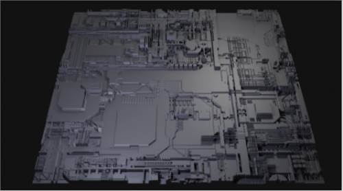
변위는 그레이스케일 이미지를 사용하여 중요한 토폴로지를 생성하는 곳입니다.
다음은 그레이스케일 “지도”의 예입니다. 참고 저는 멋진(무료) 앱인JSplacement를 사용하여 이 앱을 만들었습니다 .
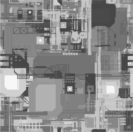
displacement map 올바르게 적용되면 그레이스케일 이미지의 밝은 영역이 어두운 영역보다 “높습니다”.